Difference between revisions of "DNA Melting Part 2: Lock-in Amplifier and Temperature Control"
Steven Nagle (Talk | contribs) (→Add heater controller board) |
Steven Nagle (Talk | contribs) (→Add heater controller board) |
||
| Line 63: | Line 63: | ||
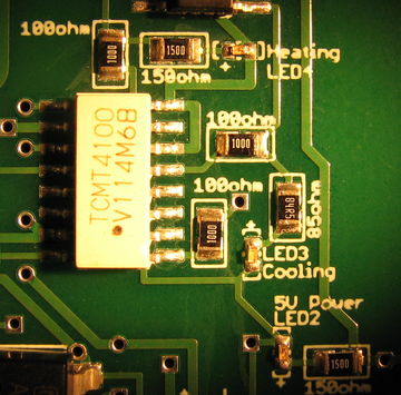
[[Image:HeaterCoooler_PCB_StatusLEDs.JPG|360 px|thumb|left|Heating, Cooling, and Logic power stats LEDs]] | [[Image:HeaterCoooler_PCB_StatusLEDs.JPG|360 px|thumb|left|Heating, Cooling, and Logic power stats LEDs]] | ||
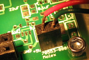
| − | [[Image:HeaterCoooler_PCB_5V.JPG| | + | [[Image:HeaterCoooler_PCB_5V.JPG|300 px|thumb|right|5 V Logic power connection]] |
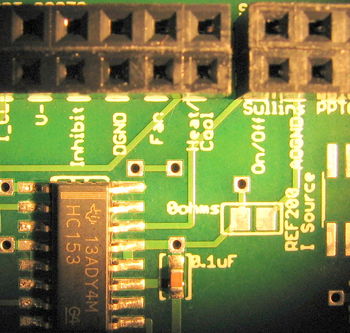
Using the reference images above, make connections between your PCB and your DAQ cable, your fan, and also your 5 V power at your breadboard. The most convenient spot would be to tap into the location of the power connection for your blue LED. The points of connection are labeled on the board, as shown in each close-up image. | Using the reference images above, make connections between your PCB and your DAQ cable, your fan, and also your 5 V power at your breadboard. The most convenient spot would be to tap into the location of the power connection for your blue LED. The points of connection are labeled on the board, as shown in each close-up image. | ||
Revision as of 19:40, 5 November 2011
| |
This page is being revised. To be finalized by November 6th, 2011 -Steven |
Overview of Part 2
Hardware changes
Possibly adjust your optics based on results in Part 1
Add LED driver
Add heater control board
Make new connections to DAQ
Add high-pass filter and possibly adjust gains in your amplifier
Software changes
Inserted lock-in amplifier in Labview VI
Inserted temperature controller in Labview VI
(Talk about possibility of using Arduino)
Why use a lock-in amplifier?
Fundamentals
Show simulation of noise sources
Reference lock-in demo
Update your electrical system
LED driver
The LED used in this lab can consume 1.5 Amps of current when driven to its full range, but this is more than 10x the light you will need. In fact, you will need only roughly 100 mA, but even this low current is 50x what the analog voltage output sources in the DAQ systems are capable of driving[1][2]. And even if there were enough current available, the steepness of a diode's I-V curve results in large swings in current for small changes in supply voltage. LED radiant flux is proportional to current, so a current source tends to provide a more stable light output.
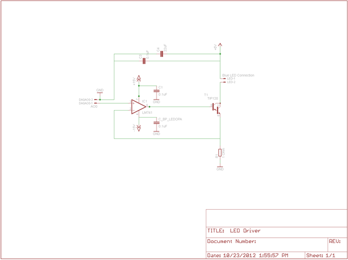
To implement a current source to drive your LED, you will be using a Darlington Transistor [3]. This is a special device in which one transistor drives another to provide higher input-output current gain. At the LED current levels for your instrument, the TIP120 will be providing a current gain of about 500. A transistor [4] is a three terminal device in which the voltage or current at one terminal controls the voltage across, or current through, the other two terminals. In our case, the TIP120 acts like one BJT consisting of a Base, Emitter, and Collector, and should be wired into the circuit shown in the diagram. We will use the base contact of our TIP120 to accept a small amount of current from an op-amp, which will cause the TIP120 to conduct a much larger current between it's collector and emitter, in turn allowing nearly the same level of current to flow through the LED.
As described in lecture, the op-amp will be used to linearize the behavior of the TIP120 and the LED. Here the LED and transistor are inside a feedback loop extending from the output of the op-amp, through the base-emitter conduction path in the TIP120, through the LED, and back from the top of the 1 Ohm resistor, whose voltage drop is thus fed-back to the negative input node of the op-amp, completing the loop. Recall that this is simply a buffer implementation, with gain of 1. Here the feedback voltage is directly proportional to the LED current. Notice that in this way the current through the LED is exactly equal to the voltage applied to the op-amp positive input by the DAQ. (Remember the golden rules.)
Note: if the LED is too bright then the sample will become photobleached very quickly. In the Labview VI for Part 2, you are able to set the voltage supplied to the op-amp.
Note also that the voltage to the LED stil comes from the fixed 5V supply on your lab station's INSTEK GPS-3303 power supply, and the op-amps still operate on +/– VCC (+/-15V in your setup).
Amplifier gain adjustments and high-pass
Add heater controller board
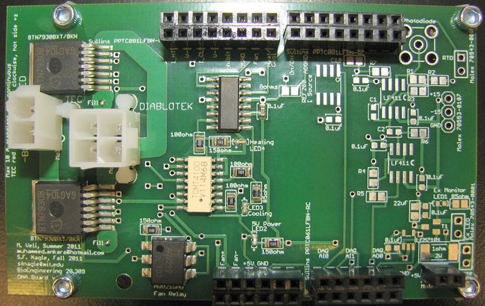
In order to control a slow ramp up and ramp down in block and sample temperature, a pulse width modulator (PWM) heater/cooler printed circuit board (PCB) has been provided for you. Once the correct connections have been made, you will be able to control your block temperature using the Labview VI with minimal input on your part. It is not required that you learn the details of the heater/cooler controller design and operation, but if you want to know more, please talk to an Instructor or TA.
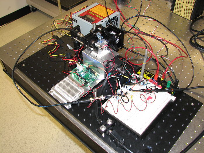
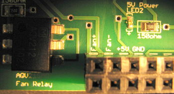
Using the reference images above, make connections between your PCB and your DAQ cable, your fan, and also your 5 V power at your breadboard. The most convenient spot would be to tap into the location of the power connection for your blue LED. The points of connection are labeled on the board, as shown in each close-up image.
In the DAQ connections inset, the Fan connection is a 0 or 5 V signal sent by your DAQ, controlled by DNA_Melting_Lock-in.vi provided for you on the course share in the Students/Labs/DNA Melting folder. The fan will turn on automatically when you first start-up this VI, and it will turn on when either the temperature profile enters the cool-down phase or when you clock on the cool-down override button in the VI. The fan is necessary to help your heatsink dissipate the waste heat that is pumped from the top side of the TEC stack during cooling operations.
The Heat/Cool connection is a 0 or 5 V signal, also sent by the DAQ and controlled by the VI, that tells the heater/cooler logic circuits to either heat (high, 5 V) or cool (low, 0 V). The DGND slot next to the Fan and Heat/Cool connections should be connected to the digital ground of the DAQ, which is provide using the bare wire from your DAQ connector, as described in the handout.
Nex, the On/Off connection also accepts a 0 or 5 V signal from the DAQ. However this signal is a square wave of varying duty cycle. This forms the heart of the PWM control approach. When the signal is high, the large BTN7930 power switches are configured to allow current to flow through the TEC. The Heat/Cool signal controls the direction of power flow, either for heating or cooling. When the On/Off signal is low, no power flows through the switches. A control loop inside the Labview VI implements a Proportional-Integral-Derivative (PID) controller to control the both the On/Off pulse widths and the Heat/Cool signal in order to maintain a desired temperature, or follow a desired temperature profile in time.
Finally, connect your TEC and the computer power supply for the TEC and fan. Connect your TEC to the 2-pin Molex male connector on the left of the board using a Part 2 (red/black wires) female connector provided on the counter top near the breadboards and previously-supplied Part 1 (Black/White wires) connector. Connect these Part 2 TEC wires to your TEC stack using wire nuts as before. Be sure to connect red-to-red and black-to-black. For the "Diablotek" connector labeled on the PCB, first verify that the Diablotek computer power supply is not switched on, then use the 4-pin connector from the Diablotek that IS NOT labeled for Part 1. This will be a white connector, in contrast to the black connector that you used for Part 1. Do not yet switch on the Diablotek.
Update your data acquisition system
New inputs to heater controller and LED controller
Use lock-in version of Labview VI
Part 2 Experimental procedure
Groups of different sample types: 3 knowns, one unknown of from that set
Measure SNR
Lab manual sections
- DNA Melting: Simulating DNA Melting - Basics
- DNA Melting Part 1: Measuring Temperature and Fluorescence
- DNA Melting Report Requirements for Part 1
- DNA Melting: Simulating DNA Melting - Intermediate Topics
- DNA Melting Part 2: Lock-in Amplifier and Temperature Control
- DNA Melting Report Requirements for Part 2
References
- ↑ Datasheet for the USB-6212
- ↑ Datasheet for the USB-6341
- ↑ Darlington Transistor
- ↑ Using a transistor

