|
|
| Line 20: |
Line 20: |
| | | | |
| | ===Rails=== | | ===Rails=== |
| | + | Optical rails are a convenient way to mount components that have to slide back and forth. Components mount to clams that sit on the rail. A thumbscrew on the clamp locks it in position. |
| | + | |
| | + | You will mount all of the components on an optical rail in order to easily adjust the distances between them. Here's what you need: |
| | + | |
| | * 1 x RLA1800 dovetail optical rails | | * 1 x RLA1800 dovetail optical rails |
| | * 4 x RC1 rail carriers | | * 4 x RC1 rail carriers |
Revision as of 04:19, 2 September 2014
20.309: Biological Instrumentation and Measurement

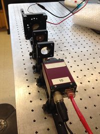
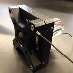
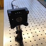
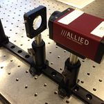
Simple imaging aparatus mounted on an optical rail.
Overview
This lab exercise will introduce you to some of the optical components that you will use in the microscopy lab. You will build an apparatus that includes an LED illuminator, an object with precisely spaced markings, a lens, and a CCD camera. You will measure the image distance for several different object distances. Using the MATLAB Image Acquisition Tool, you will record images and use them to measure magnification. Finally, you will compare your measurements to the values given by the lens makers' formula derived in class.
Build the apparatus
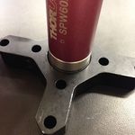
The first step is to gather the materials you need. The lists below include part numbers and descriptive names of all the components in the apparatus. It is likely that you will find some of the component names not-all-that-self-explanatory. Most of the parts come from a company called ThorLabs. If you have a question about one of the components, the ThorLabs website can be very helpful. For example, if the procedure calls for an SPW602 spanner wrench and you have no idea what such an thing might look like, try googling the term: "thorlabs SPW602". You will find your virtual self just a click or two away from a handsome photo and detailed specifications.
Orientation
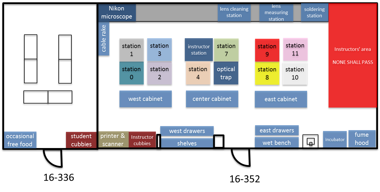
There are more than 15,000 bits and pieces in the 20.309 lab — many of them look alike. It's important to learn your way around the lab so you don't spend a lot of time looking for things. Take a walk around the whole lab and just check things out. Spend at least five minutes poking around. Read the poster near the Nikon microscope and check out the Studley tool chest. See! Wasn't that worthwhile?
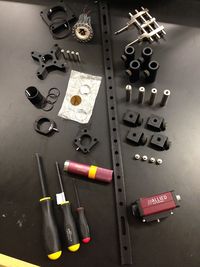
Now go ahead and gather all the parts you will need.
Rails
Optical rails are a convenient way to mount components that have to slide back and forth. Components mount to clams that sit on the rail. A thumbscrew on the clamp locks it in position.
You will mount all of the components on an optical rail in order to easily adjust the distances between them. Here's what you need:
- 1 x RLA1800 dovetail optical rails
- 4 x RC1 rail carriers
Posts and mounts
Posts, bases, and screws are located on the west credenza. Lens tubes and cage plates are on the center credenza. Cage rods are on the center bench.
- 1 x LCP01 cage plate
- 2 x SM2RR retaining rings
- 1 x LCP02 cage plate adapter
- 4 x ER1 cage assembly rod
- 6 x SM1RR retaining rings
- 1 x SM1L10 lens tube
- 1 x SM1RC lens tube slip ring
- 1 x CP02 cage plate
Screws and posts
- 6 x 1/4-20 x 5/16" cap screws
- 4 x PH2-ST post holders
- 4 x TR2 optical posts
- 4 x 8-32 set screws
- 1 x 1/4-20 set screw
- 8 x 4-40 set screws
Optics
- 1 x plano-convex f = 25 mm lens
- 1 x LB1811 biconvex f = 35 mm lens
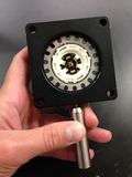
Object
- 1 x R1DS1N 1951 USAF test target
Optoelectronics
Tools
Here is a list of the tools you will need:
- 1 x SPW602 spanner wrench
- 1 x SPW801 adjustable spanner wrench
- 1 x 3/16 balldriver for 1/4-20 cap screws
- 1 x 9/64 balldriver
- 1 x 0.050" hex balldriver for 4-40 set screws
Things that should already be (and stay at) your lab station
- 1 x Manta CCD camera
- 1 x Calrad 45-601 power adapter for CCD
- 1 x ethernet cable connected to the lab station computer
|
|
|
|
- Secure the optical rail on the optical table using two 1/4-20 x 5/16 cap screws and the 3/16 hex balldriver.
- Prepare four sliding posts, each by attaching one RC1 rail carrier to one PH2-ST post holder with one 1/4-20 x 5/16 cap screws.
|
|
|
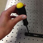
Mount the LED light source:
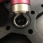
- In the LCP01 cage plate, the LED will get sandwiched in-between two SM2RR retaining rings. First screw in one SM2RR only 1 mm deep.
- Next place the LED above it.
- Finally tighten down the second SM2RR using the SPW801 adjustable spanner wrench. The SPW801 can be opened until its width matches the SM2RR diameter, the separation between the ring's notches.
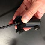
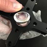
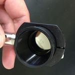
- In the LCP02 cage plate adapter, screw in on SM1RR 3 mm deep.
- Carefully (use lens paper unsparingly to protect the lens surface) place the 25 mm plano-convex lens above it, with the hemisphere facing down yet not touching any potentially damaging surface.
- Tighten down a second SM1RR using the SPW602 spanner wrench, whose guide flanges sit in the ring's notches to prevent any scratching of the lens's optical surface.
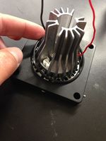
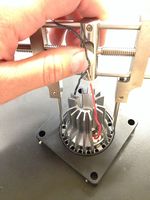
- Attach the LCP01 cage plate (holding the LED) to the LCP02 adapter (holding the 25 mm condenser lens), using the 0.050" hex balldriver to secure four ER1 rods with eight 4-40 set screws.
- Affix a TR2 optical post to the LCP01 cage plate (holding the LED).
- Slide in the LED assembly along the optical rail.
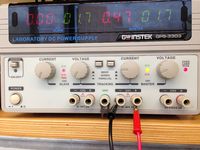
Power the LED light source:
- The red LED will be connected to a DC power supply. Ensure that the current limit on the power supply (CH1) is set to a value below 0.5 A.
- Connect channel CH1 to the red and black threads of the LED, using alligator clip cables.
- Turn on the power supply, and press its Output button to light the LED.
- Adjust the LED brightness using the power supply's Voltage knob.
|
|
|
|
|
|
|
|

|
|
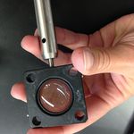
Mount the object (US Air Force target 1951):
- Tighten the R1DS1N 1951 USAF test target in-between two SM1RR retaining rings inside the SM1L10 lens tube, using the SPW602 spanner wrench. (This procedure should be reminiscent of the insertion of the 25 mm hemispherical lens in the cage plate adapter.)
- Slide in the lens tube through the SM1RC slip ring. By rotating the lens tube, you will be able to modify orientation of the object.
- Lock the lens tube in place using the 9/64 hex balldriver.
- Affix a TR2 optical post to the SM1RC slip ring (holding the USAF target).
- Slide in the object assembly along the optical rail.
Mount the lens (f = 35 mm):
- Tighten the LB1811 biconvex f = 35 mm lens in-between two SM1RR retaining rings inside the CP02 cage plate.
- Affix a TR2 optical post to the CP02 cage plate (holding the lens).
- Slide in the lens assembly along the optical rail.
|
|
|
|
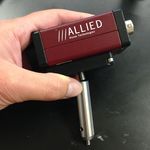
Mount the CCD camera:
- Affix a TR2 optical post directly to the CCD camera plate using the 1/4-20 set screw.
- Slide in the camera assembly along the optical rail.
- Connect the CCD to the computer using a red ethernet cable.
- Power up the CCD using the Calrad 45-601 power adapter.
|
| Vertically align the LED, object, lens, and camera assemblies.
|
Visualize, capture, and save images in Matlab
|
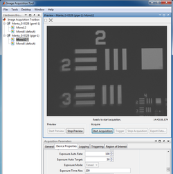
- Log on to the computer, launch Matlab, and run imaqtool.
- Select the Manta GigE Mono 12" hardware in the left bar.
- The Start Preview button will bring up a window of the live image from the CCD camera.
- Move the lens and USAF 1951 target object to produce a focused image.
- Under the Device Properties tab, optimize the Exposure Time Abs field for good contrast without pixel saturation.
- Measure the distance $ S_o $ from the target object to the lens and the distance $ S_i $ from the lens to the CCD active imaging plane.
- Does the lens maker formula $ {1 \over S_o} + {1 \over S_i} = {1 \over f} $ apply as it should when the image focus is optimized?
|
|
- Save images in Matlab:
- Make sure you limit to 1 the number of Frames Per Trigger in the General tab of the Acquisition Parameters;
- Use the Start Acquisition and Export Data buttons;
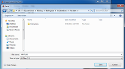
- Navigate to the Student Data\ Fall 2014\ directory accessible from the computer desktop to save your data files remotely on a server you'll be able to browse from your home computer.
- The file extension will be .MAT (e.g. 1951target_01.mat). The variable within this file (e.g. im01) will represent the image as a 492x656 matrix of 16-bit integers.
|
Examine images in Matlab
|
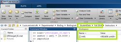
- To display the image in Matlab, use the imshow command:
- Include the Student Data\ Fall 2014\ directory to your Matlab path.
- When the 12-bit numbers from the camera get transferred to the computer, they are converted to 16-bit numbers. 16-bit numbers can represent a range of values from 0-65535. This leaves a considerable portion of the number range unoccupied. Because of this, if you type imshow( im01 ), you will see an image that looks almost completely black.
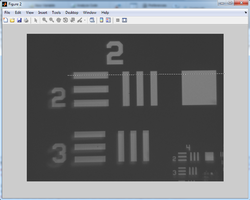
- Adjust the image to fill the full range by typing imshow( 16.0039 * im01 ).
- Note: 16.0039 equals 16 + 1/256. This factor maps values in the range 0-4095 to 0-65535.
|
|
- Determine the distance (in pixels) between two specific points in the image:
- Either use the Data Cursor Tool to display the X and Y coordinate of your mouse pointer,
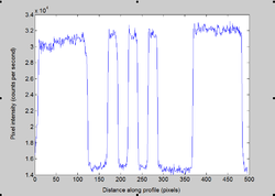
- or use the interactive improfile function from the Matlab command window, which lets you trace a segment across the active figure (visualized as a dotted line) and generates a plot of pixel intensity vs. pixel position along the segment in a new figure.
- This manipulation allows you to calculate the image size $ h_i $, taking into account the CCD pixel size: 7.4 μm x 7.4 μm.
- Confirm the corresponding object size $ h_o $:
- Refer to the specification sheet of the USAF 1951 test target, pages 5 and 8 in particular.
- The 1" R1DS1N 1951 USAF test target includes elements of groups 2 and 3.
- Example: Element 2 in Group 2 has 4.49 cycles (= line pairs) per millimeter. So 2 line pairs from Element 2 in Group 2 span 2 ÷ 4.49 = 0.4454 mm = 445.4 μm.
- Do both magnification relationships $ M = {h_i \over h_o} = {S_i \over S_o} $ match ?
|
|
Plot and discuss your results
- Repeat these measurements of $ S_o $, $ S_i $, $ h_o $, and $ h_i $ for several values of $ S_o $.
- Plot $ {1 \over S_i} $ as a function of $ = {1 \over f} - {1 \over S_o} $.
- Plot $ h_i $ as a function of $ h_o $.
- What sources of error affect your measurements?
- What is the uncertainty of your magnification measurement?
Optical microscopy lab
Code examples and simulations
Background reading


