Difference between revisions of "Optics Bootcamp"
From Course Wiki
MAXINE JONAS (Talk | contribs) m |
MAXINE JONAS (Talk | contribs) |
||
| Line 12: | Line 12: | ||
:<math>M = {h_i \over h_o} = {S_i \over S_o}</math> | :<math>M = {h_i \over h_o} = {S_i \over S_o}</math> | ||
* become familiar with image acquisition and distance measurement using the Matlab software. | * become familiar with image acquisition and distance measurement using the Matlab software. | ||
| + | |||
| + | |||
| + | ==Build the optomechanical testing apparatus== | ||
| + | |||
| + | {|class="wikitable" | ||
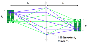
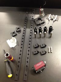
| + | |align="left" colspan="2"|To measure the relationship between <math>S_o</math> (the distance between the object and the lens), <math>S_i</math> (the distance between the lens and the image), <math>h_o</math> (the size of the object) and <math>h_i</math> (the size of the image), you'll need the following components: | ||
| + | * 1 x SPW602 spanner wrench | ||
| + | * 1 x SPW801 adjustable spanner wrench | ||
| + | * 1 x 3/16 balldriver for 1/4-20 cap screws | ||
| + | * 1 x 0.050" hex balldriver for 4-40 set screws | ||
| + | * 2 x RLA1800 dovetail optical rails | ||
| + | * 4 x RC1 rail carriers | ||
| + | * 8 x 1/4-20 x 5/16" cap screws | ||
| + | * 4 x PH2-ST post holders | ||
| + | * 4 x TR2 optical posts | ||
| + | * 4 x 8-32 set screws | ||
| + | * 1 x red LED | ||
| + | * 1 x LCP01 cage plate | ||
| + | * 2 x SM2RR retaining rings | ||
| + | * 1 x LCP02 cage plate adapter | ||
| + | * 1 x plano-convex f = 25 mm lens | ||
| + | * 4 x ER1 cage assembly rod | ||
| + | * 8 x 4-40 set screws | ||
| + | * 6 x SM1RR retaining rings | ||
| + | * 1 x R1DS1N 1951 USAF test target | ||
| + | * 1 x SM1L10 lens tube | ||
| + | * 1 x SM1RC lens tube slip ring | ||
| + | * 1 x LB1811 biconvex f = 35 mm lens | ||
| + | * 1 x CP02 cage plate | ||
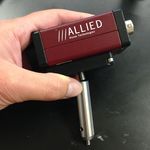
| + | * 1 x Manta CCD camera | ||
| + | * 1 x 1/4-20 set screw | ||
| + | * 1 x Calrad 45-601 power adapter for CCD | ||
| + | * 1 x ethernet cable for CCD | ||
| + | |width="200"|[[Image: 140729_OpticsBootcamp_02.jpg|frameless|200px]] | ||
| + | |width="200"|[[Image: 140730_OpticsBootcamp_3.jpg|frameless|200px]] | ||
| + | |- | ||
| + | |width="150"|[[Image: 140729_OpticsBootcamp_03.jpg|frameless|150px]] | ||
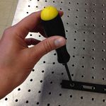
| + | |align="left" colspan="3"|* Secure the two optical rails on the optical table using four 1/4-20 x 5/16 cap screws and the 3/16 hex balldriver. | ||
| + | |- | ||
| + | |width="150"|[[Image: 140729_OpticsBootcamp_09.jpg|frameless|150px]] | ||
| + | |align="left" colspan="3"|* Prepare four sliding posts, each by attaching one RC1 rail carrier to one PH2-ST post holder with one 1/4-20 x 5/16 cap screws. | ||
| + | |- | ||
| + | |width="150"|[[Image: 140729_OpticsBootcamp_05.jpg|frameless|150px]] | ||
| + | |width="150"|[[Image: 140729_OpticsBootcamp_07.jpg|frameless|150px]] | ||
| + | |align="left" rowspan = "3" colspan="2"|'''Mount the LED light source''': | ||
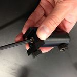
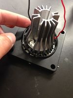
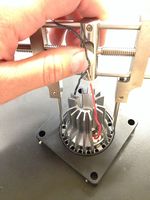
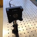
| + | * In the LCP01 cage plate, the LED will get sandwiched in-between two SM2RR retaining rings. First screw in one SM2RR only 1 mm deep. | ||
| + | * Next place the LED above it. | ||
| + | * Finally tighten down the second SM2RR using the SPW801 adjustable spanner wrench. The SPW801 can be opened until its width matches the SM2RR diameter, the separation between the ring's notches. | ||
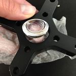
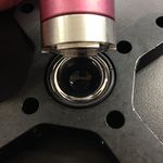
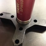
| + | * In the LCP02 cage plate adapter, screw in on SM1RR 3 mm deep. | ||
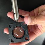
| + | * Carefully (use lens paper unsparingly to protect the lens surface) place the 25 mm plano-convex lens above it, with the hemisphere facing down ''yet not touching any potentially damaging surface''. | ||
| + | * Tighten down a second SM1RR using the SPW602 spanner wrench, whose guide flanges sit in the ring's notches to prevent any scratching of the lens's optical surface. | ||
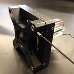
| + | * Attach the LCP01 cage plate (holding the LED) to the LCP02 adapter (holding the 25 mm condenser lens), using four ER1 rods secured by eight 8-32 set screws. | ||
| + | * Affix a TR2 optical post to the LCP01 cage plate (holding the LED). | ||
| + | * Slide in the ''LED'' assembly along the optical rail. | ||
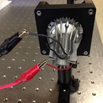
| + | '''Power the LED light source''': | ||
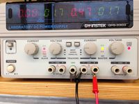
| + | * The red LED will be connected to a DC power supply. Ensure that the current limit on the power supply (CH1) is set to a value below 0.5 A. | ||
| + | * Connect channel CH1 to the red and black threads of the LED, using alligator clip cables. | ||
| + | * Turn on the power supply, and press its ''Output'' button to light the LED. | ||
| + | * Adjust the LED brightness using the power supply's ''Voltage'' knob. | ||
| + | |- | ||
| + | |width="150"|[[Image: 140729_OpticsBootcamp_10.jpg|frameless|150px]] | ||
| + | |width="150"|[[Image: 140729_OpticsBootcamp_11.jpg|frameless|150px]] | ||
| + | |- | ||
| + | |width="150"|[[Image: 140729_OpticsBootcamp_12.jpg|frameless|150px]] | ||
| + | |width="150"|[[Image: 140729_OpticsBootcamp_13.jpg|frameless|150px]] | ||
| + | |- | ||
| + | |width="150"|[[Image: 140729_OpticsBootcamp_08.jpg|frameless|120px]] | ||
| + | |width="150"|[[Image: 140729_OpticsBootcamp_15.jpg|frameless|150px]] | ||
| + | |align="left"|[[Image: 140730_OpticsBootcamp_1.jpg|frameless|200px]] | ||
| + | |width="150"|[[Image: 140730_OpticsBootcamp_2.jpg|frameless|150px]] | ||
| + | |- | ||
| + | |width="150"|[[Image: 140730_OpticsBootcamp_4.jpg|frameless|150px]] | ||
| + | |align="left" colspan="3"|'''Mount the object (US Air Force target 1951)''': | ||
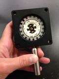
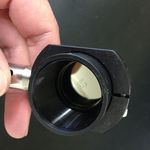
| + | * Tighten the R1DS1N 1951 USAF test target in-between two SM1RR retaining rings inside the SM1L10 lens tube, using the SPW602 spanner wrench. (This procedure should be reminiscent of the insertion of the 25 mm hemispherical lens in the cage plate adapter.) | ||
| + | * Slide in the lens tube through the SM1RC slip ring. By rotating the lens tube, you will be able to modify orientation of the ''object''. | ||
| + | * Affix a TR2 optical post to the SM1RC slip ring (holding the USAF target). | ||
| + | * Slide in the ''object'' assembly along the optical rail. | ||
| + | |- | ||
| + | |width="150"|[[Image: 140729_OpticsBootcamp_16.jpg|frameless|150px]] | ||
| + | |align="left" colspan="3"|'''Mount the lens (f = 35 mm)''': | ||
| + | * Tighten the LB1811 biconvex f = 35 mm lens in-between two SM1RR retaining rings inside the CP02 cage plate. | ||
| + | * Affix a TR2 optical post to the CP02 cage plate (holding the lens). | ||
| + | * Slide in the ''lens'' assembly along the optical rail. | ||
| + | |- | ||
| + | |width="150"|[[Image: 140729_OpticsBootcamp_17.jpg|frameless|150px]] | ||
| + | |width="150"|[[Image: 140729_OpticsBootcamp_18.jpg|frameless|150px]] | ||
| + | |align="left" colspan="2"|'''Mount the CCD camera''': | ||
| + | * Affix a TR2 optical post directly to the CCD camera plate using the 1/4-20 set screw. | ||
| + | * Slide in the ''camera'' assembly along the optical rail. | ||
| + | * Connect the CCD to the computer using a red ethernet cable. | ||
| + | * Power up the CCD using the Calrad 45-601 power adapter. | ||
| + | |- | ||
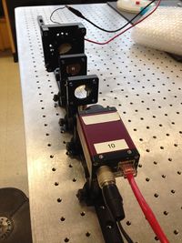
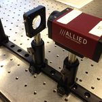
| + | Vertically align the ''LED'', ''object'', ''lens'', and ''camera'' assemblies. | ||
| + | |} | ||
| + | |||
{{:Optical microscopy lab wiki pages}} | {{:Optical microscopy lab wiki pages}} | ||
Revision as of 21:36, 30 July 2014
Through this exercise, you will
- learn the basics of mounting, aligning and adjusting optical components;
- verify the lens maker and the magnification formulae:
- $ {1 \over S_o} + {1 \over S_i} = {1 \over f} $
- $ M = {h_i \over h_o} = {S_i \over S_o} $
- become familiar with image acquisition and distance measurement using the Matlab software.
Build the optomechanical testing apparatus
Optical microscopy lab
Code examples and simulations
- Converting Gaussian fit to Rayleigh resolution
- MATLAB: Estimating resolution from a PSF slide image
- Matlab: Scalebars
- Calculating MSD and Diffusion Coefficients
Background reading
- Geometrical optics and ray tracing
- Physical optics and resolution
- Optical aberrations
- Aperture and field stops
- Optical detectors, noise, and the limit of detection
- Manta G032 camera measurements
- Understanding log plots
References

