Difference between revisions of "Optical Microscopy Part 2: Fluorescence Microscopy"
Steven Nagle (Talk | contribs) (→Add laser illumination path to your microscope) |
Steven Nagle (Talk | contribs) (→Add laser illumination path to your microscope) |
||
| Line 67: | Line 67: | ||
#* [[Image:20.309 130816 DichroicMirrorMount2.png|center|thumb|600px|Dichroic mirror mount]] | #* [[Image:20.309 130816 DichroicMirrorMount2.png|center|thumb|600px|Dichroic mirror mount]] | ||
#* Ask an instructor for help if you need to clean a dichroic mirror or barrier filter. Dichroics have delicate, exposed coatings and must be cleaned with extra care. | #* Ask an instructor for help if you need to clean a dichroic mirror or barrier filter. Dichroics have delicate, exposed coatings and must be cleaned with extra care. | ||
| − | # Use four black, plastic #4/40 screws to hold the cube optic mount (B5C) on the cage cube (C6W) | + | # Use four black, plastic #4/40 screws to hold the cube optic mount (B5C) on the cage cube (C6W). |
#* Tighten the screws enough so that the cube optic mount holds its adjustment, but can still be rotated. | #* Tighten the screws enough so that the cube optic mount holds its adjustment, but can still be rotated. | ||
#* Make sure to block the (small percentage of) excitation laser light that will be transmitted through the dichroic mirror with some black lab tape affixed to the B5C cube optic mount. | #* Make sure to block the (small percentage of) excitation laser light that will be transmitted through the dichroic mirror with some black lab tape affixed to the B5C cube optic mount. | ||
Revision as of 14:34, 31 January 2014

Overview
In this part of the microscopy lab, you will add epi-fluorescence imaging capability to your microscope. You will use a 5 mW, green (λ=532 nm) laser to illuminate fluorescent samples and a dichroic mirror to reflect the laser light toward the objective lens. When illuminated by the laser, the fluorescent samples will emit light in the orange/red region of the visible spectrum (550-610 nm). The dichroic mirror reflects green light but allows red light to pass through to the tube lens and CCD camera.
Because the illumination intensity is typically be 5 or 6 orders of magnitude greater than the emitted fluorescence, it is crucial to virtually eliminate excitation photons from the image plane. The dichroic mirror allows a substantial amount of green light to pass. The barrier filter attenuates green light by 5 orders of magnitude. It is essential for making good images.
Transmission spectra for filters similar to the ones you will use are shown in figure below.

Since the laser is a narrowband source, an excitation filter is not needed.
You will image a fluorescence reference slide and fluorescent microspheres of several sizes. Using the image of the fluorescence reference slide and a dark image, you will correct images to compensate for nonuniform illumination. Using an image of the smallest fluorescent microspheres, you will measure the resolution of your microscope.
The figure below shows how the physical layout of the completed fluorescence microscope relates to its block diagram.
 20.309 microscope block diagram |
 20.309 student's microscope |
|---|
Background reading
Lab Procedures
Laser safety
| |
You will use a 5mW, 532 nm laser with focusing optics in this lab. Do not begin working with the laser until you are familiar with laser safety procedures. If you missed laser safety training, see an instructor. |
While you work on this part of the lab, keep these laser safety best practices in mind:
- Use the correct laser safety eyewear. Always check the marking on the goggles.
- Know the beam path at all times.
- Your microscope directs the laser light upward.
- Do not allow the unattenuated laser beam to shine on the ceiling. Stop the beam if you are not using an ND filter.
- Never put your face directly above the objective.
- Use an OD = 2 neutral density filter to reduce the laser power to a safe level when making adjustments.
- Remove jewelry and reflective clothing items.
- Confine the beam inside lens tubes.
- Use a stop to prevent uncontained beams.
- Turn of the laser when you are using reflective tools.
- Never point the laser toward other people.
- Disable lasers when they are not in use.
Add laser illumination path to your microscope
- Go over your design with one of the instructors before you start building.
- Use cage rods to construct a cage of appropriate size for the beam expander and excitation tube lens (L3, L4, and L5).
- For maximum flexibility in positioning, removing, and reinstalling optics, use 3 cage rods instead of 4. Use a cage plate (CP02) for each lens. Mount the lens in a 1/2" lens tube (SM1L05) so it can be easily removed or installed.
- Add the two turning mirrors to the end of the cage.
- Use a thick cage plate (CP02T) only to join 2 cages. (You will use a total of two CP02T plates in your microscope.) Don't use CP02T to mount lenses — there are not enough of them in the lab to use this way. It is easy to tell the difference. CP02T has 8 set screws and is roughly twice as thick as the CP02; CP02 has 4 set screws.
- Use a cube optic mount (B5C) to mount dichroic mirror DM on a kinematic platform (B4C) . Place the kinematic platform in the cage cube (C6W).
- The first surface of the dichroic should face the laser.
- Some dichroics have an arrow indicating the first surface. If not, to ascertain which surface has the coating, watch the reflection of a corner of a piece of lens paper as it touches the mirror. On the first surface, the corner and its reflection will appear to touch. Held the other way, the corner and its image will appear a few millimeters apart.
- Mount the dichroic so that the first surface lies on exactly a diameter of the B5C mount.
- The mounting bracket should not stand in the way of the rotation of the kinematic stage.
- Use the clear plastic #4/40 screws affix the dichroic mirror without deforming nor scratching its surface.
- Hold the screwdriver at the tip to avoid slipping and scratching the dichroic. The screwdriver will instantly scratch the dichroic.
-
 Dichroic mirror mount
- Ask an instructor for help if you need to clean a dichroic mirror or barrier filter. Dichroics have delicate, exposed coatings and must be cleaned with extra care.
- The first surface of the dichroic should face the laser.
- Use four black, plastic #4/40 screws to hold the cube optic mount (B5C) on the cage cube (C6W).
- Tighten the screws enough so that the cube optic mount holds its adjustment, but can still be rotated.
- Make sure to block the (small percentage of) excitation laser light that will be transmitted through the dichroic mirror with some black lab tape affixed to the B5C cube optic mount.

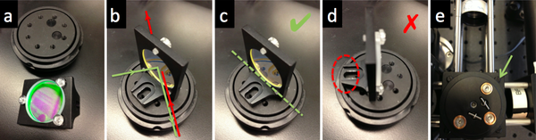
Align the laser illumination path
- Remove L3, L4, L5, and the objective lens L1.
- Mount the laser.
- Insert a neutral density filter (ND filter) between the laser and M2 to reduce the laser power to a safe level for adjustment.
- Remove jewelry. Turn of the laser before using reflective tools.
- Turn on the laser. Use a beam stop until the laser position is set. Adjust the laser position so that the laser shines near the middle of M2.
- Adjust M2 and M3 to center the laser light in the cage.

- Use two CPA1 alignment targets to gauge beam alignment.
- Adjust the dichroic mirror DM so that the beam will enter the middle of the objective lens.
- Use a DG10 mounted frosted-glass alignment disk with a pinhole to show the optical center of the vertical beam path.
- Verify that the centered beam is perpendicular to the floor. If the beam is at an angle, verify that the dichroic mirror DM is mounted on a diameter of the rotating mount.
- Insert the beam expander lenses, L3 and L4. Adjust the separation between L3 and L4 to achieve a collimated beam.
- It may be necessary to make small adjustments to M2 and M3 to recenter the beam.
- Replace the excitation tube lens L5 and the objective lens L1. Adjust the position of L5 for best beam collimation.
- The product of beam divergence and diameter is constant. L5 and L1 shrink the beam, causing increased divergence. The beam emerging from the objective will likely appear to grow in size as it propagates, even when the lenses are in their optimal positions.
- It may be necessary to make small adjustments to M2 and M3 to recenter the beam.
- Use a fluorescence reference slide to center the field of view and to optimize the uniformity of illumination.
- Make sure to use an ND filter when you use the fluorescence reference slide. The slide bleaches quickly at high intensities and you will not get a good image.
- Put a barrier filter in the afocal part of the imaging path.
- Center the camera's FOV in the objective's FOV.
- If the laser light emerges from the objective at an angle, double-check your alignment and dichroic mounting.
- The barrier filter has delicate, exposed metal coatings. Ask an instructor for help if you need to clean it.
Fluorescence imaging
In this part of the lab, you will make images of two sizes of microspheres and correct them for nonuniform illumination. In order to do the correction, you will need a reference image and a dark image in addition to the image of the sample. Take the reference image as close as possible in time to the sample images. Don't make any adjustments to your microscope between capturing the reference image and the sample image. Adjusting the camera exposure between the reference and sample images is okay. Use 12-bit imaging mode to get the best results. Save your images in a format that preserves all 12 bits.
- Put in an ND filter and take an image of the reference slide with the 40X objective.
- Use the histogram display of the camera software (function imhist in Matlab) to be certain that the image is exposed correctly.
- Take a dark image.
- Turn off the illuminator.
- Remove the ND filter and image the samples.
- Perform flat-field correction on the images.
- Divide the image by a normalized version of your reference image minus the dark image.
- Include the original, reference, and flat-field corrected images in your lab report.
Measuring resolution
One of the most commonly used definitions of resolution is the distance between two point sources in the sample plane such that the peak of one source’s image falls on the first minimum of the other source’s image. This suggests a procedure for measuring resolution: image a point source; measure the peak-to-trough distance; and divide by the magnification. In this part of the lab, you will use this method to estimate the resolution of your microscope.
A practical problem with this method is that true point sources are difficult to come by. If you are using a telescope, stars are readily available approximate point sources. In microscopy, people usually use tiny, fluorescent beads with diameters of 100-190 nm. These beads are small enough to be considered point sources. You will use nonlinear regression to estimate the resolution of your microscope from an image of the tiny beads. Unfortunately, beads small enough for this purpose are not very bright. Imaging them can be challenging. Your microscope must be aligned very well to get good results.
You will use image processing functions to locate the beads in your image and fit a Gaussian function to them. Gaussians are more amenable to nonlinear regression than Bessel functions, and they are a very good approximation. It is straightforward to convert the Gaussian parameters to Rayleigh resolution. (See Converting Gaussian fit to Rayleigh resolution.)
- Make an image of a sample of 100 or 190 nm fluorescent beads with the 40X objective.
- Use 12-bit mode on the camera and make sure to save the image in a format that preserves all 12 bits.
- Use
imhistto ensure that the image is exposed properly.- Since there are a very small number of bright pixels, plot the histogram counts on a logarithmic scale.
- Include the image in your lab report.
- Use image processing functions to locate non-overlapping, single beads in the image.
- Use nonlinear regression to fit a Gaussian to each bead image.
- Convert the Gaussian parameters to resolution.
- Report the results in your lab report.
- This page has example MATLAB code.
- Discuss how the measured resolution compares with the theoretical value.
Example images:

Report Part 2: Microscope construction and fluorescence characterization
1. Apparatus:
- Update the block diagram description of your microscope, its photograph, and annotation of pertinent optical components and distances.
2. Procedure:
- Document the critical operations and parameters of your instrument that would be necessary for another person to replicate your work. (Assume that person has taken 309 and has access to all course materials: wiki, Stellar, lectures, problem sets, etc).
Epi-fluorescence imaging capability of your enhanced microscope
3. Data:
- Include the fluorescent reference image you made as either an image (see imshow command in Matlab) or a surface plot (see surf command in Matlab), as well as a cross-section of signal intensity across its diagonal (see improfile command in Matlab).
- Exhibit your images of the 3.26 μm and 0.84 μm fluorescent bead samples. Compare and contrast these pictures before and after flat-field correction to counteract nonuniform illumination.
- Also provide log(y) scaled histograms of at least one original and corrected image pair.
4. Analysis:
- Describe your flat-field correction procedure, from recording the reference image through applying the correction.
5. Discussion:
- Comment on your corrections and relate your results to your choices during beam expander design and construction.
- How do these choices relate to your intended experiments in weeks three and beyond?
Measured microscope resolution with 40× objective
3. Data:
- Provide a sample of the images used for resolution estimation.
- Include a figure showing how many PSF points ended up being selected to participate in the averaged resolution estimate.
- Include an overlay of the Gaussian fit to the 2D Airy disc (see plotgaussfit command in Matlab).
4. Analysis:
- Provide a bullet point outline of your data analysis methodology.
5. Results:
- Report the measured resolution of the 40× objective, as approximated by the full width half maximum (FWHM) of the Gaussian fitting.
6. Discussion:
- Discuss error sources and uncertainty in the measurement.
- Comment on measured versus theoretical value.
7. Conclusions and Future Work:
- Broach on the relevance of your fluorescence imaging and resolution deductions toward upcoming tasks in the 20.309 lab.
Optical microscopy lab
Code examples and simulations
- Converting Gaussian fit to Rayleigh resolution
- MATLAB: Estimating resolution from a PSF slide image
- Matlab: Scalebars
- Calculating MSD and Diffusion Coefficients