Assignment 1, Part 3: Building your transillumination microscope
Microscope block diagram
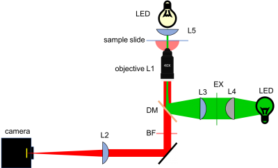
To get you started, here is a block diagram of a 20.309 microscope. Note that for Assignment 1, you will be building the brightfieqld (or transillumination) path. You should leave space for the fluorescence path, which you will complete next week.
Optical components
Below is a brief introduction to a few of the different components comprising your microscope. Various systems for optical construction are available based on rails, posts, cages, tubes, and all manner of little, metallic bits. The 20.309 microscope is constructed chiefly from cage and lens tube components made by a company called ThorLabs. The structure should be rigid, and the components sufficiently tightened so that your optics remain aligned even after moving your microscope. Understanding how all of the components work together can be daunting. Ask about any components that perplex you.
Lenses
Plano-convex spherical lenses are available with focal lengths of 25, 50, 75, 100, 125, 150, 175, and 200 mm. Plano-concave lenses with focal lengths of -30 and -50 are also available. It is best to mount most optics in short (e.g. 0.5") lens tubes. It is acceptable to mount a lens between the end of a tube and a tube ring or between two tube rings. In most cases, the convex side of the lens faces toward the collimated beam; the planar side goes toward the convergent rays.
- Tip: Verify all optics before you use them by determining the focal length with a ruler. You can use the lens measuring station. Alternatively, you can use the ceiling fluorescent lamps as a light source and measure the exact distance between the lens(es) assessed and the lamp's image. Can you imagine a simple rig to evaluate negative focal lengths (of plano-concave lenses for instance)?
- Tip: As you install lenses into your microscope, put a piece of tape on the lens tube showing focal length and orientation. This will help you both during construction and put-away. Save the lens storage boxes and return components to the correct boxes when you are done.
- Handle lenses only by the edges. If a lens is dirty, first remove grit with a blast of clean air or CO2. Clean the lens by wiping with a folded piece of lens paper wetted with a drop of methanol. (Do not touch the part of the tissue you use for cleaning with your fingers.) In some cases, it may be helpful to hold the folded lens tissue in a hemostat. Ask an instructor if you need help.
Objective lenses
Please see the Nikon Introduction to Microscope Objectives at their excellent MicroscopyU website.
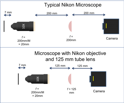
There are three objective lenses available in the lab: a 10×, a 40×, and a 100×. All of these are designed to use a 200 mm tube lens to form an image on the camera. An adapter ring converts the objective mounting threads to the SM1 threads used by the lens tube system.
- Working distance (WD) is the distance between the front objective lens surface and the cover slip, and so it is also approximately the distance to the front focal plane. In order to focus an image at the back focal plane of the tube lens, i.e., on the CCD array, the sample plane must coincide with the front focal plane in a 4f microscope arrangement. The stage is added to hold the sample in this plane.
- The 100× objective is designed to be used with immersion oil. When using the 100× objective, place a drop of oil directly on the tip on the objective. Bring the drop in contact with the slide cover glass. After use, clean off the remaining oil by wicking it away with lens paper or a Kim-wipe. Do not put samples away dirty.
- Note that the back focal plane (BFP) of the objective does not necessarily coincide with the rear of the objective housing. In fact, for the Nikon 40x objective the BFP is close to the blue ring. You will find its actual location when aligning the laser path in Part 2. The 200 mm distance labeled between the back of the objective housing and the tube lens is a recommendation from Nikon to enable optimal imaging. For details on the importance and origin of this distance please ask an instructor.
Sample stage
A precision Newport X/Y/Z stage[1] with a sample holder mounted on a post, or a Thorlabs Max312D stage, also with a sample holder, is available at each lab station. The Newport stage setup is top-heavy. Avoid accidents by ensuring that the post base is always attached to an optical breadboard or table. Leave the stage at the lab station when you are done with it. For the Thorlabs stages, it is still a good idea to bolt them down so that your area of interest (AOI) stays in your microscope field of view (FOV).
All stage axes have limited adjustment range, especially the Thorlabs stages. To deal with this, it is best to leave the stage base bolts and sample holder bolts loose and move the sample holder in x, y and z to roughly find your AOI. Once you are on or near your AOI, tighten the bolts and use the micrometers to center your image. One trick here is to get the z clamped first, then deal with x and y.
CCD camera
The microscope you will build does not have an eyepiece for direct visual observation. Instead, images will be captured with a CCD camera[2]. Its monochrome (black and white) sensor contains a grid of 656×492 square pixels that measure 7.4 μm on a side. An adapter ring converts the C-mount thread on the camera to SM1.
Design
Sketch out the design for your microscope on paper (or print out the above diagram). For this part of the lab, you can just draw the bright field illumination path. Label all the optical elements (lenses, mirrors, microscope objectives, and camera), distances, lens specifications, and orientations.
- Some elements must be positioned precise distances apart; other distances are not critical. Use ray-tracing to determine when this is the case. Which distances in your bright-field microscope will be critical? Which will be forgiving or unessential? Which will change with each objective lens (10×, 40× and 100×)?
- Which sections of the light path can be open (strut-based structure, cage rods)? Which would better enclosed (Thorlabs lens tubes)?
- In what way will the illumination LED color affect your design? your results?
- Which lens will you use between the LED and the sample for bright field transmitted light imaging?
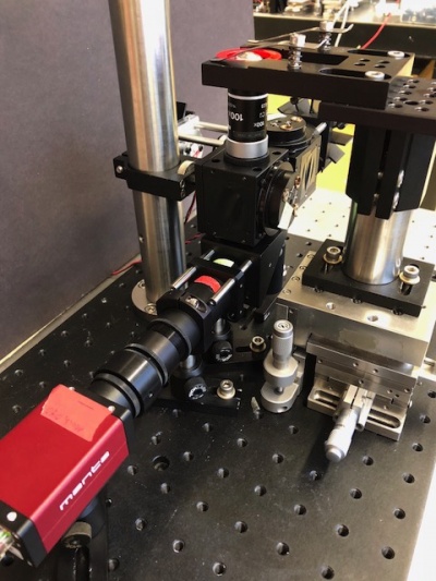
Next, take a look at the example microscope in the lab. This microscope is here for your reference, but please do not touch, alter, or remove parts from the example microscope.
Can you identify all the components of your diagram? Try to think about the purpose of each component, and why it is laid out a particular way. Once you're satisfied that you understand the big picture, it's time to build your own!
A few tips to keep in mind:
- Reproduce the general layout of the example microscope: it grants compactness and allows your device to be a stand-alone breadboard-transportable microscope.
- Even though you're first focusing on the bright-field imaging leg of your microscope, take into consideration some requirements pertinent to the fluorescence imaging elements you'll add to your system next week:
Cite error: <ref> tags exist, but no <references/> tag was found


