Williams: PSF and Deconvolution Lab 2
Contents
Hardware & Software SPecifications
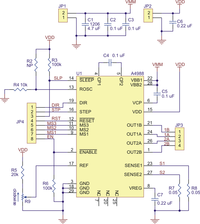
- Pololu A4983 Stepper Motor Driver Carrier with Voltage Regulators
- Thorlabs 8 mm Travel Stepper Motor Actuator[2]
- Matlab
- Matlab Image Acquisition Toolbox[3]
- Matlab Allied Vision Technologies Adaptor[4]
- National Instruments USB Data Acquisition (DAQ)
- Epi-fluorescence Microscope[6] with parts from Thorlabs
- Submicron beads, small enough to be considered point sources
MicroStepping Driver
The microstepper driver was wired on a standard on a standard bread board. We used the 5V source on the pcb to serve as the Reference(Ref). The signals to MS1,MS2,MS3,STEP, and SLEEP were inputted digital (using the output changes of the DAQ). The ENABLE port was used in conjunction with wires 1 and 3 of the stepper motor to regulate when the user has the ability to move the z-axis of the microstepper stage. When the stage is about the be moved past it's z-upper or lower bounds, the circuit between wires 1 and 3 open ( infinite impedance ). This fact was used to regulate when ENABLE was receiving the 5V from the REF port. ENABLE-bar is originally set to digital local 0 when it is receiving the full 5V so it is disabled ( i.e. digital logical 1). When the stage is trying to be moved pasts its z bounds, the wires open and ENABLE see . This is called a ... The digital output connected to SLEEP-bar is used to control whether movement in the z-axis of the stage is locked ( i.e you are not able to focus it ) or unlocked/sleeping ( you are able to focus the stage). When the digital signal is 1(true) the microstepper driver is not sleeping and when the digital signal is 0(false) you are able to control the stage. STEP was originally controlled with an analog signal but it was mentioned that STEP is should receive only digital signals. I'm uncertain about whether this is true. Because the logical behind the STEP function should be that it steps whenever it sees a rising edge, and if the reference value ( i.e. the value for true is set to 5V) in my opinion you should be able to feed a analog signal into STEP and have it respond so that it steps whenever it sees a rising signal from 0 to 5. The MS1,MS2 and MS3 were all used to control the angle the magnet rotates per step six. At full step the stepper rotates 1.8 degrees. For our purposes we used the smallest step size ( 16th-step ) which corresponds to 0.2 degrees per step.
Code
- Microstepper Script
GUI for Z-stack imaging
script of GUI for z-stack imaging;
Code
Image Acquisition
PSF and Deconvolution
ImageJ
Experiements:
Results
