Difference between revisions of "Optical trap"
(→Instrument overview) |
|||
| Line 14: | Line 14: | ||
==Instrument overview== | ==Instrument overview== | ||
===Block diagram=== | ===Block diagram=== | ||
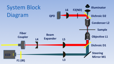
| − | [[Image:OpticalTrapBlockDiagram.PNG|thumb|right| | + | [[Image:OpticalTrapBlockDiagram.PNG|thumb|right|400px|Optical trap block diagram.]] |
| + | In the diagram, a high-NA objective lens (L1) performs the dual functions of imaging the sample and focusing the trapping laser. L1 is a 1.25 NA, 100X (2mm equivalent focal length), infinity corrected, oil immersion objective lens with a working distance of 0.65 mm. The back aperture of L1 is 5mm in diameter. | ||
| + | |||
| + | Steering mirror M1 and tube lens L3 complete the imaging path. L3 is a 1" diameter, uncoated plano convex lens with a focal length of 200 mm. L3 forms an image of the sample plane on the detector of a CCD camera placed at a distance of 200 mm. (For best performance, the distance between L3 and the CCD imager should be accurate.) | ||
| + | |||
| + | The trapping laser beam emerges from a fiber coupler with a diameter of approximately ??mm. Lenses L4 and L5 (focal lengths ?? and ??, respectively) implement a Galilean telescope that expands the beam by a factor of 4. To minimize aberrations and reflections, L4 and L5 are IR-coated achromatic doublet lenses. | ||
| + | |||
| + | L7 focuses an image of the LED illuminator at the backplane of the condenser, L2, to provide collimated transillumination. | ||
| + | |||
===Physical layout=== | ===Physical layout=== | ||
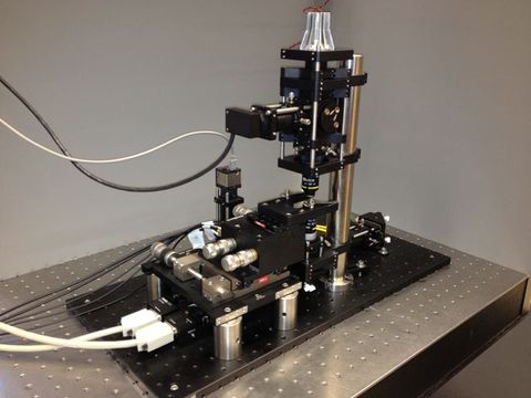
[[Image:OpticalTrapLayout.PNG|thumb|right|480px|Optical trap layout.]] | [[Image:OpticalTrapLayout.PNG|thumb|right|480px|Optical trap layout.]] | ||
Revision as of 02:25, 7 August 2012
Introduction
Optical tweezers can exert measurable forces on micron-scale dielectric particles. This capability offers a unique and valuable tool for manipulating and measuring cell components at the single molecule level. For example, optical traps have been used extensively to investigate the mechanical properties of biological polymers and the force generation mechanisms of molecular motors. In many studies, optical tweezers apply force to functionalized microspheres, which act as convenient handles attached to molecules of interest.
To make quantitative force measurements, the instrument records the displacement of a trapped microsphere over time. For small displacements, the exerted force is very nearly proportional to displacement, so the trap can be modeled as a linear spring. Accurate force and position measurements depend on careful calibration of the position detector responsivity, G, and the trap stiffness α, also called the spring constant. The stiffness is a function of trapping laser power, bead size, bead composition, and optical properties of the sample.
This page has tips for setting up and aligning an optical trap. It discusses three methods for obtaining the spring constant and two methods for measuring α.
Instrument overview
Block diagram
In the diagram, a high-NA objective lens (L1) performs the dual functions of imaging the sample and focusing the trapping laser. L1 is a 1.25 NA, 100X (2mm equivalent focal length), infinity corrected, oil immersion objective lens with a working distance of 0.65 mm. The back aperture of L1 is 5mm in diameter.
Steering mirror M1 and tube lens L3 complete the imaging path. L3 is a 1" diameter, uncoated plano convex lens with a focal length of 200 mm. L3 forms an image of the sample plane on the detector of a CCD camera placed at a distance of 200 mm. (For best performance, the distance between L3 and the CCD imager should be accurate.)
The trapping laser beam emerges from a fiber coupler with a diameter of approximately ??mm. Lenses L4 and L5 (focal lengths ?? and ??, respectively) implement a Galilean telescope that expands the beam by a factor of 4. To minimize aberrations and reflections, L4 and L5 are IR-coated achromatic doublet lenses.
L7 focuses an image of the LED illuminator at the backplane of the condenser, L2, to provide collimated transillumination.
Physical layout
Summary of calibration methods
| Method | Equation | QPD Responsivity | Stage Responsivity | Solvent Viscosity | Particle Diameter | Temperature | Technical Noise |
|---|---|---|---|---|---|---|---|
| $ R_{QPD} $ | $ R_{stage} $ | $ \eta $ | $ d $ | $ T $ | |||
| Equipartition | $ \frac{K_B T}{\langle R_{QPD} V_{qpd} \rangle ^ 2} $ | inverse square | none | none | none | linear and indirect (viscosity change) | systematic decrease |
| PSD | $ \left. {6 \pi^2 \eta d \, f_0} \right. $ | none | none | linear | linear | indirect (viscosity change) | small |
| Stokes | $ \langle \frac{3 \pi \eta d \, R_{stage} \, ^{d V_{stage}} / _{dt}} {R V_{qpd}} \rangle $ | inverse | linear | linear | linear | indirect (viscosity change) | none |
Setup and alignment
Remove the optics
Collimating and adjusting the fiber port
Initial laser alignment
Beam expander coarse adjustment
Condenser adjustment
Connecting the piezo stage
Fine adjusting the beam expander
<html> <script type="text/javascript" src="http://html5.kaltura.org/js"></script> <script type="text/javascript">
 mw.setConfig('EmbedPlayer.AttributionButton',false);
 mw.setConfig('EmbedPlayer.EnableOptionsMenu',false);
</script> <object name="ttvplayer" id="ttvplayer" type="application/x-shockwave-flash" allowScriptAccess="always" allowNetworking="all" allowFullScreen="true" height="336" width="544" data="http://www.kaltura.com/index.php/kwidget/wid/_203822/uiconf_id/1898102/entry_id/1_tojxf237/"><param name="allowScriptAccess" value="always" /><param name="allowNetworking" value="all" /><param name="allowFullScreen" value="true" /><param name="bgcolor" value="#000000" /><param name="movie" value="http://www.kaltura.com/index.php/kwidget/wid/_203822/uiconf_id/1898102/entry_id/1_tojxf237/"/><param name="flashVars" value="autoPlay=false&streamerType=rtmp"/><a href="http://ttv.mit.edu">MIT Tech TV</a></object>
</html>
OTKB software
Starting the software
<html> <script type="text/javascript" src="http://html5.kaltura.org/js"></script> <script type="text/javascript">
 mw.setConfig('EmbedPlayer.AttributionButton',false);
 mw.setConfig('EmbedPlayer.EnableOptionsMenu',false);
</script> <object name="ttvplayer" id="ttvplayer" type="application/x-shockwave-flash" allowScriptAccess="always" allowNetworking="all" allowFullScreen="true" height="336" width="544" data="http://www.kaltura.com/index.php/kwidget/wid/_203822/uiconf_id/1898102/entry_id/1_i5yndloo/"><param name="allowScriptAccess" value="always" /><param name="allowNetworking" value="all" /><param name="allowFullScreen" value="true" /><param name="bgcolor" value="#000000" /><param name="movie" value="http://www.kaltura.com/index.php/kwidget/wid/_203822/uiconf_id/1898102/entry_id/1_i5yndloo/"/><param name="flashVars" value="autoPlay=false&streamerType=rtmp"/><a href="http://ttv.mit.edu">MIT Tech TV</a></object> </html>
Calibration
Measuring R by scanning a stuck bead
PSD method
Equipartition method
Stokes method
<html> <script type="text/javascript" src="http://html5.kaltura.org/js"></script> <script type="text/javascript">
 mw.setConfig('EmbedPlayer.AttributionButton',false);
 mw.setConfig('EmbedPlayer.EnableOptionsMenu',false);
</script> <object name="ttvplayer" id="ttvplayer" type="application/x-shockwave-flash" allowScriptAccess="always" allowNetworking="all" allowFullScreen="true" height="336" width="544" data="http://www.kaltura.com/index.php/kwidget/wid/_203822/uiconf_id/1898102/entry_id/1_vzh3tc1f/"><param name="allowScriptAccess" value="always" /><param name="allowNetworking" value="all" /><param name="allowFullScreen" value="true" /><param name="bgcolor" value="#000000" /><param name="movie" value="http://www.kaltura.com/index.php/kwidget/wid/_203822/uiconf_id/1898102/entry_id/1_vzh3tc1f/"/><param name="flashVars" value="autoPlay=false&streamerType=rtmp"/><a href="http://ttv.mit.edu">MIT Tech TV</a></object> </html>


