Difference between revisions of "Optical Microscopy Part 1: Brightfield Microscopy"
MAXINE JONAS (Talk | contribs) (→Practice) |
Steven Nagle (Talk | contribs) (→CCD camera) |
||
| Line 57: | Line 57: | ||
====CCD camera==== | ====CCD camera==== | ||
| − | The microscope you will build does not have an eyepiece for direct visual observation. Instead, images will be captured with a CCD camera<ref>[http://www.alliedvisiontec.com/ | + | The microscope you will build does not have an eyepiece for direct visual observation. Instead, images will be captured with a CCD camera<ref>[http://www.alliedvisiontec.com/emea/products/cameras/gigabit-ethernet/manta/g-032bc.html Allied Manta G032B]</ref>. Its monochrome (black and white) sensor contains a grid of 656×492 square pixels that measure 7.4 μm on a side. An adapter ring converts the C-mount thread on the camera to SM1. |
====Samples to be imaged by bright-field microscopy==== | ====Samples to be imaged by bright-field microscopy==== | ||
Revision as of 20:11, 22 October 2013

Don't you just buy a [expletive deleted] microscope?[1]
Contextual Background
- Read background references
- Geometrical optics and ray tracing
- Physical optics and resolution
- Lectures 1 through 9 of the 20.309 class
- From Nikon MicroscopyU
- Conjugate planes in optical microscopy (includes transmitted and reflected (epi) illumination)
- Snell's law
- Resolution
Components of the 20.309 microscope

Rigid optical construction
The structure of your microscope will be built from a combination of cage and lens tube components from ThorLabs. (See the ThorLabs online catalog for more details. Print catalogs are available in the lab.) Be sure you understand how to use cage cubes (C4W), cube optic mounts (B5C), and kinematic mounting plates (B4C). Please ask about any components you are not sure how to use them (also find more specific details below).
Simple lenses
Plano-convex spherical lenses are available with focal lengths of 25, 50, 75, 100, 125, 150, 175, and 200 mm. Plano-concave lenses with focal lengths of -30 and -50 are also available. It is best to mount most optics in short (e.g. 0.5") lens tubes. It is acceptable to mount a lens between the end of a tube and a tube ring or between two tube rings. In most cases, the convex side of the lens faces toward the collimated beam; the planar side goes toward the convergent rays.
- Tip: Verify all optics before you use them by determining the focal length with a ruler. Use the ceiling fluorescent lamps as a light source and measuring the exact distance between the lens(es) assessed and the lamp's image. Can you imagine a simple rig to evaluate negative focal lengths (of plano-concave lenses for instance)?
- Tip: As you install lenses into your microscope, put a piece of tape on the lens tube showing focal length and orientation. This will help you both during construction and put-away. Save the lens storage boxes and return components to the correct boxes when you are done.
- Handle lenses only by the edges. If a lens is dirty, first remove grit with a blast of clean air or CO2. Clean the lens by wiping with a folded piece of lens paper wetted with a drop of methanol. (Do not touch the part of the tissue you use for cleaning with your fingers.) In some cases, it may be helpful to hold the folded lens tissue in a hemostat. Ask an instructor if you need help.
Objective lenses
Please see the Nikon Introduction to Microscope Objectives at their excellent MicroscopyU website.
There are three objective lenses available in the lab: a 10×, a 40×, and a 100×. All of these are designed for a 200 mm tube lens. An adapter ring converts the objective mounting threads to the SM1 threads used by the lens tube system.

- The back focal plane (BFP) of the objective coincides with the rear of the objective housing. This is equivalent to the focal plane of a simple lens.
- Working distance (WD) is the distance between the front end of the objective and the sample plane (when the sample is in focus). Generally, the higher the magnification, the lower the working distance.
- The 100× objective is designed to be used with immersion oil, which provides an optical medium of pre-determined refractive index (n = 1.5). When using the 100× objective, place a drop of oil on it. Bring the drop in contact with the slide cover glass. After use, clean off excess oil by wicking it away with lens paper. Do not put samples away dirty. It is not necessary to use immersion oil for thin samples such as the Air Force Target or Ronchi Ruling.
Sample stage
A precision Newport X/Y/Z stage[3] with a sample holder mounted on a post, or a Thorlabs Max312D stage, also with a sample holder, is available at each lab station. The Newport stage setup is top-heavy. Avoid accidents by ensuring that the post base is always attached to an optical breadboard or table. Leave the stage at the lab station when you are done with it. For the Thorlabs stages, it is still a good idea to bolt them down so that your area of interest (AOI) stays in your microscope field of view (FOV).
All stage axes have limited adjustment range, especially the Thorlabs stages. To deal with this, it is best to leave the stage base bolts and sample holder bolts loose and move the sample holder in x, y and z to roughly find your AOI. Once you are on or near your AOI, tighten the bolts and use the micrometers to center your image. One trick here is to get the z clamped first, then deal with x and y.
CCD camera
The microscope you will build does not have an eyepiece for direct visual observation. Instead, images will be captured with a CCD camera[4]. Its monochrome (black and white) sensor contains a grid of 656×492 square pixels that measure 7.4 μm on a side. An adapter ring converts the C-mount thread on the camera to SM1.
Samples to be imaged by bright-field microscopy
- Air Force imaging target 1951 or 1963A (find datasheets on the web)
- Slides of 7.2 μm, 3.2 μm and 1 μm silica spheres
- Ronchi ruling - a periodic pattern containing 600 line-pairs per mm
Instructions
Microscope construction
Design
Sketch out a rough design for your microscope on paper. Begin with the bright field illumination path.
- Some elements must be positioned precise distances apart; other distances are not critical. Use ray-tracing to determine when this is the case. Which distances in your bright-field microscope will be critical? Which will be forgiving or unessential? Which will change with each objective lens (10×, 40× and 100×)?
- Which sections of the light path can be open (strut-based structure)? Which would better enclosed (Thorlabs tubes)?
- In what way will the illumination LED color affect your design? your results?
- Which lens will you use between the LED and the sample for bright-field transmitted light imaging?
Practice
- Please do not remove parts from the example microscope.
- On a removable breadboard affixed to the tabletop of a vibration-isolating floating table, build a bright-field imaging microscope, using the provided LED as a light source, CCD camera as a light detector, and the rigid mounting components and lenses at your disposal.
- Even though you're first focusing on the bright-field imaging leg of your microscope, take into consideration some requirements pertinent to the fluorescence imaging elements you'll add to your system next week:
- Reproduce the general layout of the example microscope: it grants compactness and allows your device to be a stand-alone breadboard-transportable microscope.
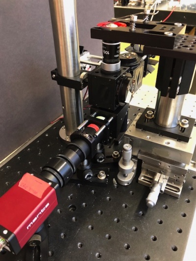 The general layout of the 20.309 microscope is compact and stand-alone; it fits and can be transported onto a breadboard
- Do insert the C4W cage cube that will later hold the dichroic mirror on while fluorescence imaging will rely. Be sure to keep the mounting struts fully recessed in the cube walls; their ends should not stick out, they would otherwise hinder maneuvers with dichroic-holding kinematic plate!
- Reproduce the general layout of the example microscope: it grants compactness and allows your device to be a stand-alone breadboard-transportable microscope.


- Set the distance between the top of the breadboard and the bottom of the silver mirror cube (just below the objective) to 7 cm. It is important to ensure your construction is compatible with either of the two distinct stage mounting platforms available in the 20.309 lab (either Newport or Thorlabs model). Note that the stages are very expensive; always lift them from the bottom.
- Verify the focal length of the lenses you selected. If you find an optic in the wrong box: identify the optic and replace it in the correct box or label the box correctly. (Ask an instructor if you can't find the right box. There are many boxes near the wire spools behind you as you stand at the wet bench.)
- Check all your lenses for cleanliness before you use them. You'll save yourself some troubleshooting time and effort down the road!
- Make sure all your components are "leveled" (horizontal, not slanted).
- Use tube rings (and never an SM1T2, SM1V01, or SM1V05) to mount optics in lens tubes.
- Use adjustable mounting components in front of the CCD camera so you can optimize and fine-tune the camera positing with respect to the imaging lens L2. Beware: never use an SM1T2 coupler without a locking ring — they are very difficult to remove if they are tightened against a lens tube or tube ring. Also put a quick-connect in your design such that the camera CCD will end up 200 mm from the back focal plane of the objective. Remember that the CCD is recessed inside the opening of the camera.

- Restrict to 3 struts only the connection between the cage cube and the last silver mirror before the CCD camera, so you can easily take in and out the barrier filter BF that will later aid fluorescence-mode microscopy.

- The Nikon objective lenses are designed to be paired with a 200 mm tube lens.
- Assume that the objectives behave as ideal plano-convex lenses.
- Fine focusing will be achieved by adjusting the height of the sample stage.
- Tip: Throughout the optical microscopy lab, start the alignment with a 10× objective but progress to 40× and 100×.
- You can use either a red or a blue LED illuminator for bright-field transmitted light imaging.
- Each group will receive their own LED. Please ask an instructor if you cannot find one.
| |
Double check your wiring before powering the LED. The LED can be damaged by excessive current. Limit the driving current to 0.5 A to protect the LED. |
Brightfield imaging
Make sure your images are not vibrating nor flickery. Otherwise, check that your optical table is effectively floating!
- To have the approximate center of the objective's field of view (FOV) correspond with the center of the CCD image, actuate both the X and Y stages, and the last mirror's knobs.
- Image the following samples using three different objectives (10×, 40×, and 100×):
- Line pairs from the Air Force imaging target 1951 or 1963A that fills your field of view (find datasheets on the web),
- Slides of 7 μm, 3.2 μm and 1 μm silica spheres,
- Line pairs from the Ronchi ruling (its periodic pattern contains 600 line-pairs per mm).
- Can you see all these samples?
- In Matlab, using the functions imaqtool and imshow (Figure_Name * 16), capture pictures of these images.
- Applying the Data Cursor tool, measure the actual magnification and field of view (FOV) of your microscope with each of the three objectives (10×, 40×, and 100×).
- Elucidate where the uncertainty of your measurements stems from, and think about tactics to improve the accuracy of your calculations. Will making multiple measurements increase the accuracy of your conclusions?
Example images:

Microscope storage
During the microscopy lab, approximately seven thousand optical components will be taken from stock, assembled into microscopes, and properly returned to their assigned places. Please observe the following:
- Store your microscope in one of the cubby holes in 16-336. If you use one of the high shelves, get somebody to help you lift.
- Keep all of the boxes for the optics you use with your instrument to simplify putting things away.
- Take a blue bin to store loose items (such as lens boxes) in.
- Stages, CCD cameras, neutral density filters and barrier filters stay at the lab station. Do not store these with your microscope.
- Return objective lenses to the drawer when you are not using them. (Do not store them with your microscope.)
- The stages are very expensive. Always lift from the bottom.
- If you break something (or discover something pre-broken for you), do not return it to the component stock. Give all broken items to an instructor. You will not be penalized for breaking something, but not reporting may be looked upon less kindly.
Report: Microscope construction and brightfield characterization
Microscope design
- Draw a block diagram of your microscope, including all optical elements and relevant distances. It is unnecessary to document the details of the mechanical construction.
- Describe your design calculations and considerations.
- Illustrate your apparatus with a photograph (optional, but nice).
Microscope characterization
Describe the transmitted bright-field performance of your microscope by calculating its magnification and field of view, with each of the three objectives (10×, 40× and 100×):
- Provide examples of transilluminated images used to calculate the magnification of the microscope. It is not necessary to show an exhaustive set of all images.
- Include a table with the following values for the 10×, 40× and 100× objectives:
- Theoretical resolution
- Actual magnification by multiple measures (Air Force Target, Ronchi Ruling)
- Actual field of view in the sample plane (FOV)
- Quantify the uncertainty on your measurements (with an appropriate number of significant decimal points!).
- After calibration, measure the size of microspheres (justify the size of the microspheres chosen for each of the objectives), and comment on the mean and uncertainty of your measurements.
Discussion on uncertainty
- Explain why some samples could not be well imaged with some objective(s), and whether the results differed from your expectations.
- Identify the limits of accuracy of your microscope. Indicate which sources of error contribute to the compounded uncertainty reported ("± s.d." or "± s.e.m."), which dominate, which can be compensated / improved on, and which are intrinsic to your microscope design.
- Recognize user- vs. instrument-based errors. Explain how multiple measurements improve (or not!) the accuracy of your calculations. Suggest possible design choices that would improve microscope performance.
Optical microscopy lab
Code examples and simulations
- Converting Gaussian fit to Rayleigh resolution
- MATLAB: Estimating resolution from a PSF slide image
- Matlab: Scalebars
- Calculating MSD and Diffusion Coefficients
Background reading
- Geometrical optics and ray tracing
- Physical optics and resolution
- Optical aberrations
- Aperture and field stops
- Optical detectors, noise, and the limit of detection
- Manta G032 camera measurements
- Understanding log plots