Difference between revisions of "Electronics written problems"
From Course Wiki
(→Conservation laws) |
(→Conservation laws) |
||
| Line 19: | Line 19: | ||
==Conservation laws== | ==Conservation laws== | ||
{| | {| | ||
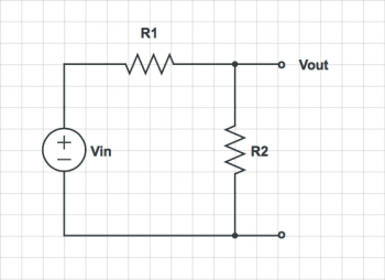
| − | |[[File:Voltage divider.png]] | + | |[[File:Voltage divider.png|350px]] |
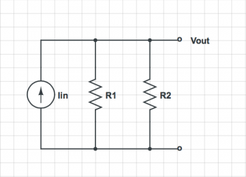
| − | ||[[File:Current divider.png]] | + | ||[[File:Current divider.png|350px]] |
|} | |} | ||
* Find the voltage at each node and the current through each element in these circuits consisting of resistors and ideal sources. | * Find the voltage at each node and the current through each element in these circuits consisting of resistors and ideal sources. | ||
Revision as of 23:15, 17 October 2018
This is Part 2 of Assignment 6.
Ideal elements
Conservation laws

|

|
- Find the voltage at each node and the current through each element in these circuits consisting of resistors and ideal sources.
Equivalent circuits
- Create a simplified version of each circuit. The simplified circuit should contain one source and one resistor. The I-V curve of the port should be the same as the original circuit.
Measuring voltage
A circuit model for a neuron in culture connected to a patch clamp apparatus consists of a time-varying voltage source in series with an output impedance of 1011 Ω. There is an oscilloscope next to the neuron with an input impedance of 106 Ω. A circuit model for the oscilloscope is a 106 Ω resistor to ground. A new UROP in the lab attempts to measure the electrical spikes produced by the neuron (called action potentials) using the oscilloscope. The oscilloscope has a noise floor of 10-3 V.
- What is the magnitude of the action potential signal after the student connects the oscilloscope?
- Does the student succeed? Why or why not?
- What is the signal to noise power ratio?
- How many times does the student curse during the measurement attempt?
- What is the minimum input impedance that a measurement device must have in order to make a high-fidelity measurement of an action potential.
Bode plots
- Draw a Bode plot for each of the circuits. Suggest a descriptive name for each (e.g. "low-pass filter" or "Phil the Powerful High-Phrequency Destroyer.")
Properties of linear systems
- For the given input signal $ x(t) $, what is the output signal $ y(t) $ in each of the circuits below?
