Bode plots and frequency response
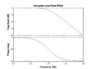
A Bode plot is a log-log representation plot of the magnitude of a transfer function versus frequency. In a Bode plot, only straight line segments are used to approximate the transfer function. At a critical or cutoff frequency, there is an abrupt change in slope in the transfer function instead of a smooth transition (e.g., from pass band to stop band).
For example, consider a simple RC low-pass filter with the transfer function is given by
- $ H(f) = \frac{V_{out}}{V_{in}} = \frac{1}{1 + j2\pi f RC} $
In this case the cutoff frequency is given by $ f_C = 1/(2\pi RC) $. In the Bode plot of this function, a straight line segment with zero slope for $ f < f_C $ represents the pass band of the filter while a line with a slope of −1 for $ f > f_C $ represents the stop band.
More examples
High-pass
- $ H(f) = \frac{j2\pi f \tau_{\rm HP}}{1 + j2\pi f \tau_{\rm HP}} $
- $ H(f) = \frac{j f / f_{\rm HP}}{1 + j f / f_{\rm HP}} $
Second-order low-pass
- $ H(f) = \left(\frac{1}{1 + j2\pi f \tau_{\rm LP}}\right)^2 $
- $ H(f) = \left(\frac{1}{1 + j f / f_{\rm LP}}\right)^2 $
Band pass
- $ H(f) = \frac{j2\pi f \tau_{\rm HP}}{1 + j2\pi f \tau_{\rm HP}} \times \frac{1}{1 + j2\pi f \tau_{\rm LP}} $
- $ H(f) = \frac{j f / f_{\rm HP}}{1 + j f / f_{\rm HP}} \times \frac{1}{1 + j f / f_{\rm LP}} $

