Assignment 8, Part 2: build a two-color microscope
In Assignment 10, we'll be imaging the nuclear response of the Hog1 protein to osmotic shock in S. Cerevisiae. To measure nuclear localization of Hog1, we need to know 1) where is Hog1? and 2) where is the nucleus? We'll answer these questions using two spectrally-separated fluorescent protein reporters: GFP (fused to Hog1) and tagRFP (fused to an mRNA binding protein we'll cal MCP). We can use the same green LED we've been using so far to excite tagRFP, but we need to add a blue LED to excite GFP.
You'll need to make the following modifications to implement two-color imaging on your microscope:
- Add a second excitation source (blue) to excite GFP
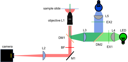
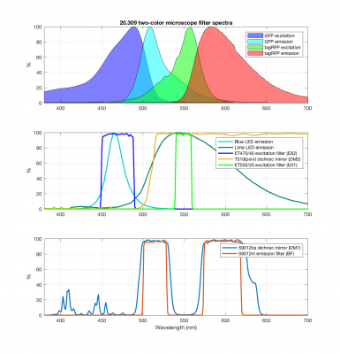
- Change the dichroic and emission filter to reflect both excitation colors and transmit the emissions for GFP and RFP.
- Implement a control circuit to be able to switch on and off the LEDs using MALTAB
Let's get started!
New block diagram and filter sets
In Assignment 3, you chose filters to measure two colors simultaneously. Since the yeast cells will not be changing dramatically over short timescales (many seconds), we will image the two different colors sequentially. In other words, only one color LED will be on at a time. This allows us to use the same camera for both images. Since we're imaging sequentially, you could imagine mechanically flipping out the dichroic and barrier filter to be suitable for either GFP or RFP. Instead, we'll use a dual band dichroic and barrier filter which will eliminates the need for moving parts in the microscope.
The new block diagram for the microscope is shown below, along with a detailed plot of the new filter spectra.
- Overview
- Part 1: feedback systems
- Part 2: fabricate a microfluidic device
- Part 3: add flow control and test your device
Back to 20.309 Main Page

