Difference between revisions of "Assignment 6, Part 1: Pre-lab questions"
Juliesutton (Talk | contribs) (Created page with "Category:Lab Manuals Category:20.309 Category:Optical Microscopy Lab {{Template:20.309}} This is Part 1 of Assignment 6. <br /> ==Prob...") |
MAXINE JONAS (Talk | contribs) (→Question 1) |
||
| (3 intermediate revisions by 2 users not shown) | |||
| Line 3: | Line 3: | ||
[[Category:Optical Microscopy Lab]] | [[Category:Optical Microscopy Lab]] | ||
{{Template:20.309}} | {{Template:20.309}} | ||
| + | __NOTOC__ | ||
This is Part 1 of [[Assignment 6 Overview| Assignment 6]]. | This is Part 1 of [[Assignment 6 Overview| Assignment 6]]. | ||
<br /> | <br /> | ||
| − | == | + | ==Question 1== |
| − | |||
| − | |||
| − | |||
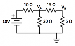
Consider the following circuit composed of a network of resistors: | Consider the following circuit composed of a network of resistors: | ||
[[Image: Circuit1.png|center|250px|thumb]] | [[Image: Circuit1.png|center|250px|thumb]] | ||
| − | + | {{Template:Assignment Turn In|message= | |
| + | <ol type="a"> | ||
| + | <li>Combining resistance values in parallel and in series, draw a simplified version of the circuit containing the given voltage source (10V) and one equivalent resistor. Label the equivalent resistance value. | ||
| + | </li> | ||
| + | <li> | ||
| + | Find the voltage values for the nodes <math>V_A</math> and <math>V_B</math> in the above diagram. | ||
| + | </li> | ||
| + | </ol> | ||
| + | }} | ||
| − | + | ==Question 2== | |
| − | = | + | {{Template:Assignment Turn In|message = Referring to the circuit shown below, what value of <math>R_L</math> (in terms of <math>R_1</math> and <math>R_2</math>) will result in the maximum power being dissipated in the load? |
| − | Referring to the circuit shown below, what value of <math>R_L</math> (in terms of <math>R_1</math> and <math>R_2</math>) will result in the maximum power being dissipated in the load? | + | }} |
| − | + | Hint: this is much easier to do if you first remove the load, and calculate the equivalent Thevenin output resistance <math>R_T</math> of the divider looking into the node labeled <math>V_{out}</math> (the [[Electronics primer]] has a section on Thevenin Equivalent circuits). Then express <math>R_L</math> for maximal power transfer in terms of <math>R_T</math>. | |
| − | Hint: this is much easier to do if you first remove the load, and calculate the equivalent Thevenin output resistance <math>R_T</math> of the divider looking into the node labeled <math>V_{out}</math>. Then express <math>R_L</math> for maximal power transfer in terms of <math>R_T</math>. | + | |
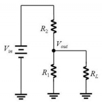
[[Image: VoltageDivider.jpg|center|200px|thumb|A voltage divider formed by <math>R_1</math> and <math>R_2</math> driving a resistive load <math>R_L</math>.]] | [[Image: VoltageDivider.jpg|center|200px|thumb|A voltage divider formed by <math>R_1</math> and <math>R_2</math> driving a resistive load <math>R_L</math>.]] | ||
| − | + | ==Question 3== | |
| − | + | ||
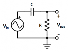
In the following circuit, R = 10 kΩ and C = 10 nF. | In the following circuit, R = 10 kΩ and C = 10 nF. | ||
[[Image: Filter1.jpg|center|220px|thumb]] | [[Image: Filter1.jpg|center|220px|thumb]] | ||
| − | + | {{Template:Assignment Turn In|message = | |
| − | + | ||
| − | + | ||
| − | + | ||
| − | + | ||
| + | <ol type="a"> | ||
| + | <li>Find the transfer function <math>{V_{out} \over V_{in}}</math>.</li> | ||
| + | <li>What type of filter is this? Justify your answer.</li> | ||
| + | <li>What is the cutoff frequency of this filter? Write your answer in units of Hz. Remember that <math>\omega = 2 \pi f </math>.</li> | ||
| + | </ol> | ||
| + | }} | ||
Note: You may find the pages on [[Impedance Analysis]] and [[Bode plots| Transfer Functions and Bode Plots]] helpful for this problem. | Note: You may find the pages on [[Impedance Analysis]] and [[Bode plots| Transfer Functions and Bode Plots]] helpful for this problem. | ||
| + | {{Template: Assignment 6 navigation}} | ||
{{Template:20.309 bottom}} | {{Template:20.309 bottom}} | ||
Latest revision as of 20:28, 3 April 2018
This is Part 1 of Assignment 6.
Question 1
Consider the following circuit composed of a network of resistors:
Question 2
| |
Referring to the circuit shown below, what value of $ R_L $ (in terms of $ R_1 $ and $ R_2 $) will result in the maximum power being dissipated in the load? |
Hint: this is much easier to do if you first remove the load, and calculate the equivalent Thevenin output resistance $ R_T $ of the divider looking into the node labeled $ V_{out} $ (the Electronics primer has a section on Thevenin Equivalent circuits). Then express $ R_L $ for maximal power transfer in terms of $ R_T $.
Question 3
In the following circuit, R = 10 kΩ and C = 10 nF.
Note: You may find the pages on Impedance Analysis and Transfer Functions and Bode Plots helpful for this problem.
Back to 20.309 Main Page.


