Cartridge Manipulation
Exploring the necessary cartridge modifications began with taking the cartridge apart. To break open the cartridge, I simply tapped lightly with a flathead screwdriver and a hammer, around the top edge of the cartridge at the intersection of the lid and the base. After tapping the screwdriver into the groove, the cover would gradually work its way off, though cracks would occur in the plastic around the top edge. These cracks did not prove detrimental to the functioning of the cartridge.
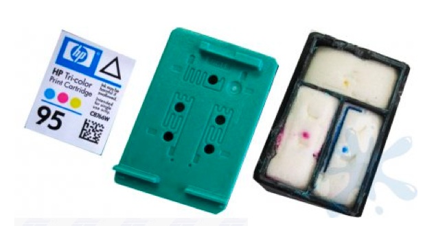
The HP5700 used HP94 black ink cartidges and HP95 color cartridges (shown below). Within both, there were sponges that held the ink. At the base of each sponge was a small well (~0.5 mL in volume) that was covered by a thin filter.
Lid removed from an HP95 color ink cartridge
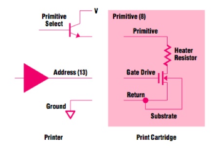
Within each cartridge is a series of tiny nozzles, each which have a small heater which allows for the creation of ink droplets. The current across the heat resistor creates a flash of high temperature, which causes instant vaporization of the substrate. A simplified schematic (courtesy of HP) is shown below. Note that additional information and a useful resource is available at http://wandel.ca/hp45_anatomy/index.html, which provides an in depth description of the dissection of an ink cartridge.
Circuit schematic of ink cartridge nozzle
In order to ensure that the cartridges could print cells, a series of experiments was necessary. Throughout these experiments, I made a series of key estimates.
Contents
Experiment 1: New Ink
Key Question Can an aqueous solution that is not the original ink flow easily through the cartridge?
Design In a simple first experiment, I removed the sponges and emptied the cartridges of their ink, washing multiple times with water to remove as much ink as possible. I then filled the chambers with about 2 mL each of different colored ink made with food dye.
Results Images came out properly printed but with the new color ink, verifying that different inks could be passed through the cartridge.
Note: It is helpful to empty the ink from a new cartridge because each cartridge has a limited printing lifetime which is tracked by the computer. Even if a cartridge has ink in it, the printer may think it is empty because it has theoretically expended enough ink to render it no longer functional.
Experiment 2: Cartridge Flow Test
Key Question How much ink must pass through the cartridge before a new ink begins flowing through the printer?
Design After cleaning out the cartridge thoroughly with water and ethanol and letting it dry, the cartridge was loaded with 2-3 mL of new dye. The printer was then printed at a maximum dpi in a solid square to determine at what point the ink would start flowing.
Results The ink created a solid patterned square after printing about 0.75 square inches.
Assuming a drop size of 50 pL, then
1200 dpi * 1200 dpi * 0.75 sq. inches = 1.08*10^6 drops
and 1.08*10^6 drops * 50 * 10^-12 L/drop = 60*10^-6 L
or about 60 microliters must pass through the cartridge for a new ink to be reliably flowing.
Experiment 3: Drying Evaluation
Key Question How long can the samples remain moist in an enclosed chamber after printing?
Design Because the cells are printed in a defined pattern, immediately adding media or broth after printing would disrupt the patterning and ruin the printed sample. Therefore, keeping the cells moist while allowing them to adhere to the sample surface is a critical step, but one can't wait too long or the cells will dry out. Some key factors affecting evaporation are:
- relative humidity - surface area of the evaporating surface - temperature of the air and of the evaporating substance - air velocity over the liquid
More specifically, evaporation rate is equal to
(mass loss rate)/(unit area) = (vapor pressure - ambient partial pressure)*sqrt( (molecular weight)/(2*pi*R*T) )
Without an accurate way to measure the temperature of the printed sample, I opted to minimize other parameters to try to prolong the drying process--namely, by covering the sample, I attempted to maximize local humidity while minimizing air flow. However, note that surface area is also examined briefly in the Cell Printing Experimentation section.
The word MIT was printed onto glass coverslips, which were immediately lined with a ring of vacuum grease and sealed with a second cover slip. The word was printed in a variety of different dpi densities and the samples were left to sit for a variety of time intervals. After the proper time interval, samples were opened and checked for moisture by simply smudging the ink.
Results The longest evaluated time was 30 minutes, for which the max dpi was able to stay moist. The chart below describes all the outcomes. Moisture is rated on a scale of 1-5, with 5 being very liquidy and 1 being completely dry.
Drying evaluation, by the official "Smudge Technique"
Experiment 4: Bead Filter Evaluation
Key Question Is there a filter in the cartridge fine enough to catch the cells I am trying to print?
In many new models of printer cartridges, tiny filters have been added to catch lumps and impurities in the ink. Though I removed the visible filters from the cartridges I used, I needed to confirm that there was not a second filter further down in the ink path.
Design I used 3 Micron fluorescent beads (a diameter similar to the size of an E. coli) to show that particles that size could successfully pass through the cartridge. A solution of approximately 10^7 beads/mL (a dilution comparable to that of the cells) was created by making a 1:50 dilution of 1% by weight Nile Red beads. About 0.5 mL of the solution was printed onto glass coverslips and dried, before mounting and examining under the demo 20.309 fluorescent microscope.
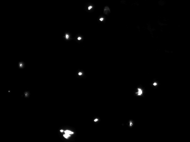
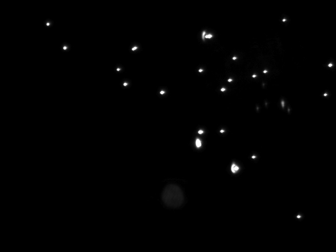
Results Beads were seen, proving that they could in fact be printed. Defined patterns could be distinguished, and clear printing boundaries were seen. However, beads were not printed with consistent density or shifted to inconsistent densities after being printed.
3 Micron Beads (10X) - Printing density inconsistencies and bead aggregation
3 Micron Beads (10X) - Defined printing boundaries can be seen, as in this image with the curve of the serif of an "i"; the upper right corner of the image is within the printed letter and the lower left corner is not


