Difference between revisions of "Optics Bootcamp"
(→Lab exercise 3: noise in images) |
(→Lab exercise 2: imaging with a lens) |
||
| Line 69: | Line 69: | ||
Now measure the focal length of the four lenses marked A, B, C, and D. The lenses are located near the lens measuring station. | Now measure the focal length of the four lenses marked A, B, C, and D. The lenses are located near the lens measuring station. | ||
| + | |||
==Lab exercise 2: imaging with a lens== | ==Lab exercise 2: imaging with a lens== | ||
| − | [[Image: | + | You will build something that looks like the picture below. There will be a light source (LED), an object being illuminated (a micrometer calibration slide), a lens for focusing, and a camera to view the final image. You will be able to adjust the positions of the object and lens to see what happens to the image formed on your camera. |
| + | |||
| + | [[Image: OpticsBootcampApparatus.png|thumb|400px|center|Imaging apparatus with illuminator, object, lens, and CCD camera mounted on an optical rail.]] | ||
| − | + | The first step is to gather the materials required to build the lens measuring apparatus. Look at the image above to think about the parts you will need. | |
| − | + | To help you familiarize yourself with the different components and get started, the lists below include part numbers and descriptive names of the components in the apparatus. It is likely that you will find some of the terms not-all-that-self-explanatory. Most of the parts are manufactured by a company called ThorLabs. If you have a question about any of the components, the [http://www.thorlabs.com ThorLabs website] can be very helpful. For example, if the procedure calls for an SPW602 spanner wrench and you have no idea what such a thing might look like, try googling the term: "thorlabs SPW602". You will find your virtual self just a click or two away from [http://www.thorlabs.com/thorproduct.cfm?partnumber=SPW602 a handsome photo and detailed specifications]. | |
===Optomechanics=== | ===Optomechanics=== | ||
| + | |||
These components are located in plastic bins on top of the center parts cabinet: | These components are located in plastic bins on top of the center parts cabinet: | ||
| − | * | + | * 2 x 1" Lens tube (SM1L10) |
| − | + | * 2 x Lens tube slip ring (SM1RC) | |
| − | + | * 2 x 2" Cage plate (LCP01, looks like an "O" in a square) | |
| − | * | + | * 4 x Cage plate adapter (LCP02, looks like an "X") |
| − | * | + | * 2 x 2" Retaining rings (SM2RR) |
| − | + | ||
| − | * | + | |
| − | * 2 x | + | |
These components are located on the counter above the west drawers. | These components are located on the counter above the west drawers. | ||
| − | * | + | * 3 x ER8 cage assembly rod (The last digit of the part number is the length in inches.) |
| − | * | + | * You may decide to add additional cage rods to extend the length of the ER8 rods. |
| + | * 2 x 1" Retaining rings (SM1RR) | ||
===Screws and posts=== | ===Screws and posts=== | ||
Stainless steel, ¼-20 size, socket head cap screws (SHCS), washers, posts, and post holders are located on top of the west parts cabinet. If you are unfamiliar with screw types, take a look at the main screw page on the [http://www.mcmaster.com/#screws/=tjwmu5 McMaster-Carr website]. Notice on the left side of the page that there are ''about ...'' links on the left side of the page. Click the links for more information about screw sizes and attributes. [http://www.boltdepot.com/fastener-information/printable-tools/Socket-Cap-Size-Chart.pdf This link] will take you to an awesome chart of SHCS sizes. | Stainless steel, ¼-20 size, socket head cap screws (SHCS), washers, posts, and post holders are located on top of the west parts cabinet. If you are unfamiliar with screw types, take a look at the main screw page on the [http://www.mcmaster.com/#screws/=tjwmu5 McMaster-Carr website]. Notice on the left side of the page that there are ''about ...'' links on the left side of the page. Click the links for more information about screw sizes and attributes. [http://www.boltdepot.com/fastener-information/printable-tools/Socket-Cap-Size-Chart.pdf This link] will take you to an awesome chart of SHCS sizes. | ||
| − | * | + | * 3 x Post holders (PH2) |
| − | * | + | * 3 x Optical posts (TR2) |
| − | * | + | * 3 x Mounting base (BA1) |
| − | * | + | * 3 x 8-32 set screws |
| + | * 3 x 1/4-20 x 5/16" socket cap screws | ||
* 1 x 1/4-20 set screw | * 1 x 1/4-20 set screw | ||
| + | * 4 washers | ||
| + | * 4 x 1/4-20 x 1/2" socket cap screws | ||
===Optics=== | ===Optics=== | ||
Lenses and microscope objectives are located in the west drawers. | Lenses and microscope objectives are located in the west drawers. | ||
| − | * 1 x LA1951 plano-convex, f = 25 mm lens | + | * 1 x LA1951 plano-convex, f = 25 mm lens (this will be used as a condenser for your illuminator) |
| − | * 1 x LB1811 biconvex, f = 35 mm lens | + | * 1 x LB1811 biconvex, f = 35 mm lens (this will be used to form an image of your object) |
| + | * 1 x ND filter (use this if your illumination is too bright, located on east cabinet) | ||
===Object=== | ===Object=== | ||
Imaging targets are located in a plastic bin on top of the east cabinet. | Imaging targets are located in a plastic bin on top of the east cabinet. | ||
| − | * 1 | + | * 1 Micrometer Calibration Slide (each small division is 0.01mm, each larger tick mark is 0.1mm) mounted to a cage plate adapter (LCP02) |
===Optoelectronics=== | ===Optoelectronics=== | ||
| Line 137: | Line 143: | ||
* 1 x Calrad 45-601 power adapter for CCD | * 1 x Calrad 45-601 power adapter for CCD | ||
* 1 x ethernet cable connected to the lab station computer | * 1 x ethernet cable connected to the lab station computer | ||
| + | |||
| + | ==Build the apparatus== | ||
| + | Use the image of the apparatus to think about how to put your system together. The following guidelines should help get you started. If at any point you have questions, do not hesitate to ask an instructor for help. | ||
| + | |||
| + | {|class="wikitable" | ||
| + | |width="150"|[[Image: AttachBA1.JPG|frameless|170px]] | ||
| + | |width="150"|[[Image: MountedLEDonTable.JPG|frameless|150px]] | ||
| + | |align="left" colspan="2"|'''Optical posts, post holders, and mounting bases''' | ||
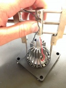
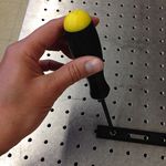
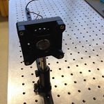
| + | Optical posts and post holders are used to mount your optical components to the table (or an optical breadboard). In addition, the post holder enables you to set the height of your optical components. In this bootcamp, you'll use the posts with their thumbscrews to ensure your components are all the same height. The images demonstrate how to use a 1/4-20 cap screw to connect the BA1 mounting base to a PH2 post holder. | ||
| + | * Secure the BA1 mounting base to the PH2 post holder using one 1/4-20 x 5/16 cap screw and the 3/16 hex balldriver. | ||
| + | * When you're ready to mount things to the table, you will use one or two washers and one or two 1/4-20 x 1/2 cap screws to secure the BA1 base to the table, as in the image on the right. | ||
| + | |- | ||
| + | |width="150"|[[Image: 140729_OpticsBootcamp_05.jpg|frameless|130px]] | ||
| + | |width="150"|[[Image: 140729_OpticsBootcamp_07.jpg|frameless|130px]] | ||
| + | |align="left" rowspan = "2" colspan="2"|'''Mount the LED light source''' | ||
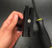
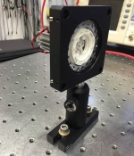
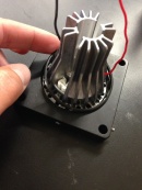
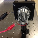
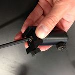
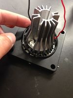
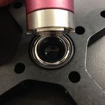
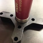
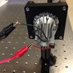
| + | * In the LCP01 cage plate, the LED will get sandwiched in-between two SM2RR retaining rings. First screw in one SM2RR only 1 mm deep. | ||
| + | * Next place the LED above it. | ||
| + | * Finally tighten down the second SM2RR using the SPW801 adjustable spanner wrench. The SPW801 can be opened until its width matches the SM2RR diameter, the separation between the ring's notches. | ||
| + | * Affix a TR2 optical post to the LCP01 cage plate (holding the LED) using an 8-32 set screw. | ||
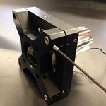
| + | * Place this optical post into a post holder and mount to the table (see previous section). | ||
| + | |||
| + | |||
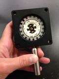
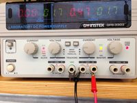
| + | '''Power the LED light source''' | ||
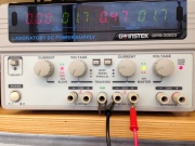
| + | * The red LED will be connected to a DC power supply. Ensure that the current limit on the power supply (CH1) is set to a value below 0.5 A! | ||
| + | * Connect channel CH1 to the red and black threads of the LED, using alligator clip cables. | ||
| + | * Turn on the power supply, and press its ''Output'' button to light the LED. | ||
| + | * Adjust the LED brightness using the power supply's ''Voltage'' knob. | ||
| + | |- | ||
| + | |width="200"|[[Image: 140730_OpticsBootcamp_1.jpg|frameless|180px]] | ||
| + | |width="200"|[[Image: 140730_OpticsBootcamp_2.jpg|frameless|130px]] | ||
| + | |- | ||
| + | |width="150"|[[Image: LensInLensTube.JPG|frameless|150px]] | ||
| + | |width="150"|[[Image: LensTubeLCP02.JPG|frameless|150px]] | ||
| + | |align="left" colspan="2" rowspan="1"|'''Mount a lens in a lens tube''' | ||
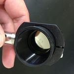
| + | We typically mount our lenses in lens tubes so that we can easily add them to or remove them from cage plates in our optical systems. | ||
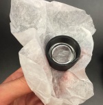
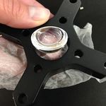
| + | * Carefully (use lens paper to protect the lens surface) place the 25 mm plano-convex lens into a 1" lens tube with the hemisphere facing up | ||
| + | * Carefully tighten down a retaining ring (SM1RR) using an adjustable spanner (SPW801) so as not to scratch the lens (the red SPW602 spanner will likely scratch the 25mm lens) | ||
| + | * Screw this lens tube into a LCP02 cage plate adapter | ||
| + | * Similarly, mount the 35mm in another 1" lens tube, but you may use the red SPW602 spanner to tighten the retaining ring. | ||
| + | |- | ||
| + | |width="150"|[[Image: TightenSetScrew.JPG|frameless|150px]] | ||
| + | |align="left" colspan="3"|'''Set up the cage rods''' | ||
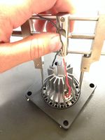
| + | We will use cage rods to frame our optical system so that we can adjust the position of cage plates by sliding them along the rods. There are 4-40 set screws that you can tighten to set the cage plate positions. Cage rods also help us to make sure our optical components are aligned to one another. | ||
| + | * Place three cage rods (ER8) through the holes in the LCP01 cage plate holding the LED. We will practice to use three cage rods instead of four, since when we use 1" cage plates, this will enable us to switch out lens tubes easily. | ||
| + | * Once the cage rods are flush against the back of the LCP01 cage plate, set their position by tightening the 4-40 set screws (see picture). | ||
| + | * Now you can slide on your other cage plates (25mm lens, object, 35mm lens) | ||
| + | * Secure the open end of your cage rods with another LCP01 cage plate mounted to an optical post, and placed into a post holder. Mount that post holder to the table, as done previously with the LED. | ||
| + | * Add an additional LCP02 cage plate adapter at the end as a setting for the camera. Tighten the set screws of the final two cage plates. | ||
| + | * Note: you may extend the ER8 rods by screwing on additional cage rods. Just make sure that the cage plates can slide across them. | ||
| + | |- | ||
| + | |width="150"|[[Image: 140729_OpticsBootcamp_17.jpg|frameless|150px]] | ||
| + | |align="left" colspan="3"|'''Mount the CCD camera''' | ||
| + | * Affix a TR2 optical post directly to the CCD camera plate using the 1/4-20 set screw. | ||
| + | * Place optical post into post holder with BA1 mounting base. | ||
| + | * Connect the CCD to the computer using a red ethernet cable. | ||
| + | * Power up the CCD using the Calrad 45-601 power adapter. | ||
| + | * Make sure the heights of the components are adjusted by adjusting the position of the optical posts. | ||
| + | |- | ||
| + | |} | ||
| + | |||
| + | ==Visualize, capture, and save images in Matlab== | ||
| + | |||
| + | [[Image: 20.309 130909 ImagingWithLens.png|right|thumb|300px]] | ||
| + | |||
| + | Now that you've learned the basics of mounting, aligning and adjusting optical components, you will through this lab exercise | ||
| + | * Verify the lens maker and the magnification formulae: | ||
| + | :<math> {1 \over S_o} + {1 \over S_i} = {1 \over f}</math> | ||
| + | :<math>M = {h_i \over h_o} = {S_i \over S_o}</math> | ||
| + | * Become familiar with image acquisition and distance measurement using the Matlab software. | ||
| + | |||
| + | {|class="wikitable" | ||
| + | |width="250"|[[Image: Imaqtool.PNG|frameless|250px]] | ||
| + | |align="left"| | ||
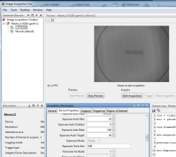
| + | * Log on to the computer, launch Matlab, and run <tt>imaqtool</tt>. | ||
| + | * Select the ''Manta_G-032B(gentl-1) Mono 12" hardware in the left bar. | ||
| + | * The ''Start Preview'' button will bring up a window of the live image from the CCD camera. | ||
| + | * Move the lens and the micrometer calibration object to produce a focused image. | ||
| + | ** Start with the object at the 2<math>f</math> position, i.e., 70 mm from the lens. | ||
| + | ** Divide additional images into an equal number with the target, the object, placed at less than and greater than 2<math>f</math> from the lens | ||
| + | * Under the ''Device Properties'' tab, optimize the ''Exposure Time Abs'' field for good contrast without pixel saturation. | ||
| + | * You may need to reduce the current in your LED, and add an ND filter after your light source to decrease its intensity | ||
| + | * Measure the distance <math>S_o</math> from the target object to the lens and the distance <math>S_i</math> from the lens to the CCD active imaging plane. | ||
| + | ** Does the lens maker formula <math> {1 \over S_o} + {1 \over S_i} = {1 \over f}</math> apply as it should when the image focus is optimized? | ||
| + | |- | ||
| + | |width="250"|[[Image: 140730_Matlab_02.png|frameless|250px]] | ||
| + | |align="left"| | ||
| + | * Save images in Matlab: | ||
| + | ** Make sure you limit to 1 the number of ''Frames Per Trigger'' in the ''General'' tab of the ''Acquisition Parameters''; | ||
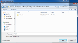
| + | ** Use the ''Start Acquisition'' and ''Export Data'' buttons; | ||
| + | ** Navigate to the ''CourseMaterials\StudentData\Spring 2016\'' directory accessible from the computer desktop to save your data files remotely on a server you'll be able to browse from your home computer. | ||
| + | *** Recall from one of the initial Stellar announcements that you must use your kerberos ID, preceded by win\, as your username. For example, Professor Nagle would enter "win\sfnagle". Use your kerberos password as well. Remember to disconnect the mapped drive when you are done at your lab station, or log out of the Windows session entirely. | ||
| + | ** The file extension will be .MAT (''e.g.'' <tt>object_01.mat</tt>), although this extension will not be visible in the Windows Explorer. The variable within this file (''e.g.'' <tt>im01</tt>) will represent the image as a 492x656 matrix of 16-bit integers. | ||
| + | |} | ||
| + | |||
| + | ==Examine images in Matlab== | ||
| + | {|class="wikitable" | ||
| + | |width="250"|[[Image: 140730_Matlab_03.png|frameless|250px]] | ||
| + | |align="left"| | ||
| + | * To display the image in Matlab, use the <tt>imshow</tt> command: | ||
| + | ** In Matlab, ''open'' your saved image file ('object_01.mat') from the ''Student Data\ Spring 2016\'' directory. | ||
| + | ** Its contents 'im01' now appear in your workspace. | ||
| + | ** When the 12-bit numbers from the camera get transferred to the computer, they are converted to 16-bit numbers. 16-bit numbers can represent a range of values from 0-65535. This leaves a considerable portion of the number range unoccupied. Because of this, if you type <tt>imshow( im01 )</tt>, you will see an image that looks almost completely black. | ||
| + | ** Adjust the image to fill the full range by typing <tt>imshow( 16.0037 * im01 )</tt>. | ||
| + | ::''Note:'' 16.0037 equals 65535 / 4095. This factor maps values in the range 0-4095 to 0-65535. | ||
| + | |- | ||
| + | |width="250"|[[Image: So_70mm_imdistline.PNG|frameless|250px]] | ||
| + | |align="left" rowspan="2"| | ||
| + | * Determine the distance (in pixels) between two specific points in the image: | ||
| + | ** Either use the ''Data Cursor Tool'' and some trigonometry to display the X and Y coordinate of your mouse pointer; | ||
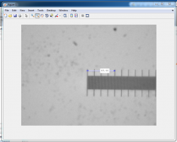
| + | ** or type <code>imdistline</code> on the console to make a very useful measuring tool appear on the image (recommended); | ||
| + | ** or use the interactive <tt>improfile</tt> function from the Matlab command window, which lets you trace a segment across the active figure (visualized as a dotted line) and generates a plot of pixel intensity vs. pixel position along the segment in a new figure. | ||
| + | ** This manipulation allows you to calculate the image size <math>h_i</math>, taking into account the CCD pixel size: 7.4 μm x 7.4 μm. | ||
| + | * Confirm the corresponding object size <math>h_o</math>: | ||
| + | ** Each small tick mark is 10 um apart | ||
| + | ** Each larger tick mark is 100 um apart | ||
| + | * Do both magnification relationships <math>M = {h_i \over h_o} = {S_i \over S_o}</math> match ? | ||
| + | |- | ||
| + | |width="250"|[[Image: 140730_Matlab_05.png|frameless|250px]] | ||
| + | |} | ||
| + | |||
| + | ==Plot and discuss your results== | ||
| + | * Repeat these measurements of <math>S_o</math>, <math>S_i</math>, <math>h_o</math>, and <math>h_i</math> for several values of <math>S_o</math>. | ||
| + | * Plot <math>{1 \over S_i}</math> as a function of <math> {1 \over f} - {1 \over S_o}</math>. | ||
| + | * Plot <math>{h_i \over h_o}</math> as a function of <math>{S_i \over S_o}</math>. | ||
| + | * What sources of error affect your measurements? | ||
| + | * Given the sources of error, how far off could your measurements of magnification be? | ||
==Build the apparatus== | ==Build the apparatus== | ||
Revision as of 21:41, 2 February 2016
Overview
You are going to build a microscope next week. The goal of the Optics Bootcamp exercise is to make that seem like a less intimidating task. The bootcamp mixes a little bit of mens and a little bit manus. It starts with a few written problems, followed by some exercises in the lab. The written problems will help you with the lab work. After you do the problems, come on by the lab. (Or do the problems in lab if you would like some help.) You will build an imaging apparatus made from some of the same optical components you will use in the microscopy lab, including an LED illuminator, an object with precisely spaced markings, a lens, and a CCD camera. You will compare measurements of object distance, image distance, and magnification to the values predicted by the lens makers' formula that was covered in class.
Problems
Problem 1: Snell's law
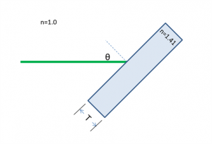
A laser beam shines on to a rectangular piece of glass of thickness $ T $ at an angle $ \theta $ of 45° from the surface normal, as shown in the diagram below. The index of refraction of the glass, ng, is 1.41 ≈√2. The index of refraction for air is 1.00.
(a) At what angle does the beam emerge from the back of the glass?
(b) When the beam emerges, in what direction (up or down) and by how much will it be displaced from its original axis of propagation?
Problem 2: chelonian size estimation
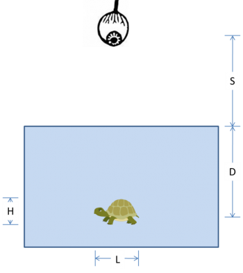
In the diagram below, an observer at height $ S $ above the surface of the water looks straight down at a turtle swimming in a pool. The turtle has length $ L $, height $ H $, and swims at depth $ D $.
(a) Use ray tracing to locate the image of the turtle. Show your work.
(b) Is the image real or virtual?
(c) Is the image of the turtle deeper, shallower, or the same depth as its true depth, $ D $?
(d) Is the image of the turtle longer, shorter, or the same length as its true length, $ L $?
(e) Is the image of the turtle taller, squatter', or the same height as its true height, $ H $?
Problem 3: ray tracing with thin, ideal lenses
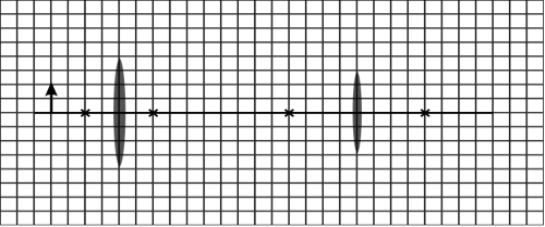
Lenses L1 and L2 have focal lengths of f1 = 1 cm and f2 = 2 cm. The distance between the two lenses is 7 cm. Assume that the lenses are thin. The diagram is drawn to scale. (The gridlines are spaced at 0.5 cm.) Note: Feel free to print out this diagram so you can trace the rays directly onto it. Or maybe use one of those fancy tablet thingies that the kids seem to like so much these days.
(a) Use ray tracing to determine the location of the image. Indicate the location on the diagram. How far to the right of lens L2 is the image located?
(b) Is the image upright or inverted? Is the image real or virtual? Explain.
(c) What is the magnification of this system?
(d) Lens L1 is made of BK7 glass with a refractive index n1 of 1.5. Lens L2 is made of fluorite glass with a refractive index n2 of 1.4. Compute the focal lengths of L1 and L2 if they are submerged in microscope oil (refractive index no = 1.5).
Problem 4: this will be useful later
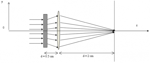
In the two-lens system shown in the figure below, the rectangle on the left represents an unspecified lens L1 of focal length $ f_1 $ separated by 0.5 cm from another lens L2 with focal length $ f_2 $ of 1 cm.
Find the value of $ f_1 $ such that all the rays incident parallel on this system will be focused at the observation plane, located at a distance d of 2 cm away from L2.
Lab exercise 1: measure focal length of lenses
Welcome to the '309 Lab. Before you get started, take a little time to learn your way around. This page gives an overview of all the wonderful resources in the lab.
Now measure the focal length of the four lenses marked A, B, C, and D. The lenses are located near the lens measuring station.
Lab exercise 2: imaging with a lens
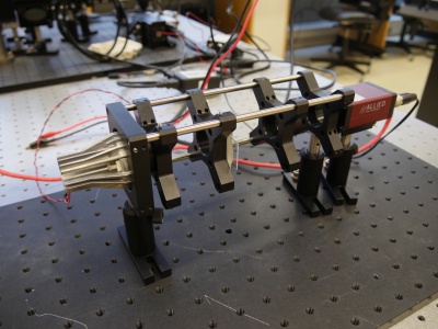
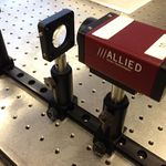
You will build something that looks like the picture below. There will be a light source (LED), an object being illuminated (a micrometer calibration slide), a lens for focusing, and a camera to view the final image. You will be able to adjust the positions of the object and lens to see what happens to the image formed on your camera.
The first step is to gather the materials required to build the lens measuring apparatus. Look at the image above to think about the parts you will need.
To help you familiarize yourself with the different components and get started, the lists below include part numbers and descriptive names of the components in the apparatus. It is likely that you will find some of the terms not-all-that-self-explanatory. Most of the parts are manufactured by a company called ThorLabs. If you have a question about any of the components, the ThorLabs website can be very helpful. For example, if the procedure calls for an SPW602 spanner wrench and you have no idea what such a thing might look like, try googling the term: "thorlabs SPW602". You will find your virtual self just a click or two away from a handsome photo and detailed specifications.
Optomechanics
These components are located in plastic bins on top of the center parts cabinet:
- 2 x 1" Lens tube (SM1L10)
- 2 x Lens tube slip ring (SM1RC)
- 2 x 2" Cage plate (LCP01, looks like an "O" in a square)
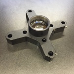
- 4 x Cage plate adapter (LCP02, looks like an "X")
- 2 x 2" Retaining rings (SM2RR)
These components are located on the counter above the west drawers.
- 3 x ER8 cage assembly rod (The last digit of the part number is the length in inches.)
- You may decide to add additional cage rods to extend the length of the ER8 rods.
- 2 x 1" Retaining rings (SM1RR)
Screws and posts
Stainless steel, ¼-20 size, socket head cap screws (SHCS), washers, posts, and post holders are located on top of the west parts cabinet. If you are unfamiliar with screw types, take a look at the main screw page on the McMaster-Carr website. Notice on the left side of the page that there are about ... links on the left side of the page. Click the links for more information about screw sizes and attributes. This link will take you to an awesome chart of SHCS sizes.
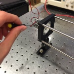
- 3 x Post holders (PH2)
- 3 x Optical posts (TR2)
- 3 x Mounting base (BA1)
- 3 x 8-32 set screws
- 3 x 1/4-20 x 5/16" socket cap screws
- 1 x 1/4-20 set screw
- 4 washers
- 4 x 1/4-20 x 1/2" socket cap screws
Optics
Lenses and microscope objectives are located in the west drawers.
- 1 x LA1951 plano-convex, f = 25 mm lens (this will be used as a condenser for your illuminator)
- 1 x LB1811 biconvex, f = 35 mm lens (this will be used to form an image of your object)
- 1 x ND filter (use this if your illumination is too bright, located on east cabinet)
Object
Imaging targets are located in a plastic bin on top of the east cabinet.
- 1 Micrometer Calibration Slide (each small division is 0.01mm, each larger tick mark is 0.1mm) mounted to a cage plate adapter (LCP02)
Optoelectronics
LEDs will be in a plastic bin on top of the center cabinet.
- 1 x red, super-bright LED (mounted)
Tools
Most of the tools are located in the drawers at your lab station. Be sure to put all of the tools you use back in their proper location.
Hex keys (also called Allen wrenches) are used to operate SHCSs. Some hex keys have a flat end and others have a ball on the end, called balldrivers. The ball makes it possible to use the driver at an angle to the screw axis, which is very useful in tight spaces. You can get things tighter (and tight things looser) with a flat driver.
- 1 x 3/16 hex balldriver for 1/4-20 cap screws
- 1 x 9/64 hex balldriver
- 1 x 0.050" hex balldriver for 4-40 set screws (tiny)
- 1 x SPW602 spanner wrench
You will also need to use an adjustable spanner wrench. The adjustable spanner resides at the lens cleaning station. There is only one of these in the lab. It is likely that one of your classmates neglected to return it to the proper place. This situation can frequently be remedied by yelling, "who has the adjustable spanner wrench?" at the top of your lungs. Try not to use any expletives. And please return the adjustable spanner wrench to the lens cleaning station when you are done.
- 1 x SPW801 adjustable spanner wrench
Things that should already be (and stay at) your lab station
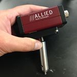
- 1 x Manta CCD camera
- 1 x Calrad 45-601 power adapter for CCD
- 1 x ethernet cable connected to the lab station computer
Build the apparatus
Use the image of the apparatus to think about how to put your system together. The following guidelines should help get you started. If at any point you have questions, do not hesitate to ask an instructor for help.
Visualize, capture, and save images in Matlab
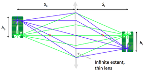
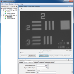
Now that you've learned the basics of mounting, aligning and adjusting optical components, you will through this lab exercise
- Verify the lens maker and the magnification formulae:
- $ {1 \over S_o} + {1 \over S_i} = {1 \over f} $
- $ M = {h_i \over h_o} = {S_i \over S_o} $
- Become familiar with image acquisition and distance measurement using the Matlab software.
Examine images in Matlab
Plot and discuss your results
- Repeat these measurements of $ S_o $, $ S_i $, $ h_o $, and $ h_i $ for several values of $ S_o $.
- Plot $ {1 \over S_i} $ as a function of $ {1 \over f} - {1 \over S_o} $.
- Plot $ {h_i \over h_o} $ as a function of $ {S_i \over S_o} $.
- What sources of error affect your measurements?
- Given the sources of error, how far off could your measurements of magnification be?
Build the apparatus
Visualize, capture, and save images in Matlab
Now that you've learned the basics of mounting, aligning and adjusting optical components, you will through this lab exercise
- verify the lens maker and the magnification formulae:
- $ {1 \over S_o} + {1 \over S_i} = {1 \over f} $
- $ M = {h_i \over h_o} = {S_i \over S_o} $
- become familiar with image acquisition and distance measurement using the Matlab software.
Examine images in Matlab

|
|
|
|
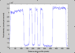
|
Plot and discuss your results
- Repeat these measurements of $ S_o $, $ S_i $, $ h_o $, and $ h_i $ for several values of $ S_o $.
- Plot $ {1 \over S_i} $ as a function of $ {1 \over f} - {1 \over S_o} $.
- Plot $ {h_i \over h_o} $ as a function of $ {S_i \over S_o} $.
- What sources of error affect your measurements?
- Given the sources of error, how far off could your measurements of magnification be?
Once you are done with your measurements, please clean up and put back all the parts.
Lab exercise 3: noise in images
Almost all measurements of the physical world suffer from some kind of noise. Capturing an image is a problem of measuring light intensity at numerous locations in space. The Manta G-032 CCD cameras in the lab measure about a quarter of a million unique locations for each image. In this part of the lab, you will quantify the noise in images made with these cameras, which are the same ones that you will use in the microscopy lab.
So what is noise in an image? Imagine that you pointed a camera at a perfectly static scene — nothing at all is changing. Then you made a movie of, say, 100 frames without moving the camera or anything in the scene or changing the lighting at all. In this ideal scenario, with a perfectly static subject and a noiseless camera, you would expect the numerical value of each pixel in all 100 of the images to be the same in every frame. Mathematically:
- $ P_{x,y}[t]=P_{x,y}[0] $,
where $ P_{x,y}[t] $ is the the pixel value reported by the camera of at pixel$ x,y $ in the frame that was captured at time $ t $. The square braces show that $ P_{x,y} $ is a discrete-time function. It is only defined at certain values of time$ t=n\tau $, where $ \tau $ is the interval between frame captures. $ \tau $ is equal to the inverse of the frame rate, or the frequency at which the images were captured.
You probably can guess that the frames will not be perfectly identical. A good way to quantify how much noise is present is to just go ahead and do the experiment: make a 100 frame movie of a static scene and then quantify how much each pixel varies over the course of the movie. Any variation in a particular pixel's value over time must be caused by random noise of one kind or another. Simple enough.
(An alternate way to do this experiment would be to simultaneously capture the same image in 100 identical, parallel universes. This will obviously reduce the time needed to acquire the data. You are welcome to use this approach in the lab, if you like.)
Variance is a very good tool for quantifying how much a quantity varies. (I really enjoyed writing that.) In case it's been a while, variance is defined as $ \operatorname{Var}(P)=\mathbf{E}\left((P-\bar{P})^2\right) $.
So here's the plan:
- Point your camera at a static scene that has a range of light intensities from bright to dark.
- Make a movie.
- Compute the variance of each pixel over time.
- Make a scatter plot of each pixel's variance on the vertical axis versus its mean value on the horizontal axis, as shown in Figure Figure 1.
The plot will reveal how noise changes with intensity. In the absence of noise, the plot will be a horizontal line on the axis. But you know that's not going to happen. How do you think the plot will look?
You can make the measurement with the same setup you put together for the previous lab exercise. Follow the detailed procedure below:
- Slide the lens close to the camera
pixelMean = mean( double( squeeze( foo ) ), 3 );
pixelVariance = var( double( squeeze( foo ) ), 0, 3 );
[counts, binValues, binIndexes ] = histcounts( pixelVariance, 250 );
binnedData = accumarray( binIndexes(:), pixelVariance(:), [], @mean );
loglog( binValues(2:end)', binnedData )


