Difference between revisions of "Lecture Notes:Modeling real systems with ideal elements"
From Course Wiki
(→Characteristics of the low pass frequency response) |
(→Characteristics of the low pass frequency response) |
||
| Line 1: | Line 1: | ||
| + | ==Op amp circuit example== | ||
| + | |||
| + | [[Image:Transimpedance amplifier with low pass.jpg|400 px|right|thumb|Transimpedance amplifier with low pass filter capacitor]] | ||
| + | |||
| + | :For convenience, let <math>s = i\omega</math>. The impedance of the capacitor is <math>\frac{1}{Cs}</math> | ||
| + | |||
| + | :Applying the golden rule: <math>v_+ = v_- = 0</math> | ||
| + | |||
| + | :KCL at the <math>V_-</math> node: <math>i_{in} + \frac{V_A}{R_1} + \frac{V_O}{1/Cs} = 0</math> | ||
| + | |||
| + | :Simplifying: <math>R_1 i_{in} + V_A + R_1 C s V_O = 0</math> | ||
| + | |||
| + | :Solving for <math>V_A</math>: <math>V_A = -R_1 i_{in} - R_1 C s V_O \quad \quad (1)</math> | ||
| + | |||
| + | :KCL at the <math>V_A</math> node: <math>-\frac{V_A}{R_1} - \frac{V_A}{R_2} + \frac{V_O - V_A}{R_3} = 0</math> | ||
| + | |||
| + | :Simplifying: <math>V_A \left ( R_2 R_3 + R_1 R_3 + R_1 R_2 \right ) = V_O \left ( R_1 R_2 \right )</math> | ||
| + | |||
| + | :Solving for <math>V_A</math>: <math>V_A = \frac{V_O ( R_1 R_2 )}{R_1 R_2 + R_1 R_3 + R_2 R_3} \quad \quad (2)</math> | ||
| + | |||
==Characteristics of the low pass frequency response== | ==Characteristics of the low pass frequency response== | ||
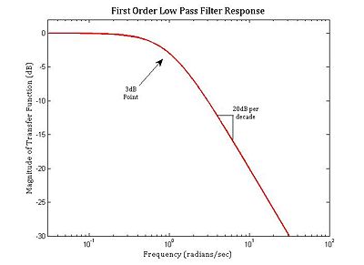
[[Image:First Order Magnitude Response.jpg|400 px|right|thumb|Magnitude of first order low pass filter transfer function H(ω) = 1/(1 + ω) in decibels]] | [[Image:First Order Magnitude Response.jpg|400 px|right|thumb|Magnitude of first order low pass filter transfer function H(ω) = 1/(1 + ω) in decibels]] | ||
| + | |||
| + | *The magnitude of the transfer function is approximately 1 at low frequ | ||
Revision as of 16:43, 23 September 2008
Op amp circuit example
File:Transimpedance amplifier with low pass.jpg
Transimpedance amplifier with low pass filter capacitor
- For convenience, let $ s = i\omega $. The impedance of the capacitor is $ \frac{1}{Cs} $
- Applying the golden rule: $ v_+ = v_- = 0 $
- KCL at the $ V_- $ node: $ i_{in} + \frac{V_A}{R_1} + \frac{V_O}{1/Cs} = 0 $
- Simplifying: $ R_1 i_{in} + V_A + R_1 C s V_O = 0 $
- Solving for $ V_A $: $ V_A = -R_1 i_{in} - R_1 C s V_O \quad \quad (1) $
- KCL at the $ V_A $ node: $ -\frac{V_A}{R_1} - \frac{V_A}{R_2} + \frac{V_O - V_A}{R_3} = 0 $
- Simplifying: $ V_A \left ( R_2 R_3 + R_1 R_3 + R_1 R_2 \right ) = V_O \left ( R_1 R_2 \right ) $
- Solving for $ V_A $: $ V_A = \frac{V_O ( R_1 R_2 )}{R_1 R_2 + R_1 R_3 + R_2 R_3} \quad \quad (2) $
Characteristics of the low pass frequency response
- The magnitude of the transfer function is approximately 1 at low frequ
