Difference between revisions of "Electronics bootcamp II: feedback systems"
From Course Wiki
(Created page with "--~~~~Category:20.309 Category:Electronics {{Template:20.309}} ==Time and frequency response of a feedback system== # Construct the circuit shown in the diagram below...") |
(→Time and frequency response of a feedback system) |
||
| Line 3: | Line 3: | ||
{{Template:20.309}} | {{Template:20.309}} | ||
==Time and frequency response of a feedback system== | ==Time and frequency response of a feedback system== | ||
| + | [[Image:Third order low-pass filter in feedback.png]] | ||
| + | |||
| + | <center> | ||
| + | {| | ||
| + | !Overdamped | ||
| + | !Critically damped | ||
| + | |- | ||
| + | | [[File:Overdamped second-order time response.png|250px]] | ||
| + | | [[File:Critically damped second-order time response.png|250px]] | ||
| + | |- | ||
| + | !Slightly underdamped | ||
| + | !Underdamped | ||
| + | |- | ||
| + | | [[File:Slightly underdamped second-order time response.png|250px]] | ||
| + | | [[File:Underamped second-order time response.png|250px]] | ||
| + | |} | ||
| + | </center> | ||
| + | |||
# Construct the circuit shown in the diagram below | # Construct the circuit shown in the diagram below | ||
Revision as of 02:20, 28 October 2018
--Steven Wasserman (talk) 21:14, 27 October 2018 (CDT)
Time and frequency response of a feedback system
| Overdamped | Critically damped |
|---|---|
| 250px | 250px |
| Slightly underdamped | Underdamped |
| 250px | 250px |
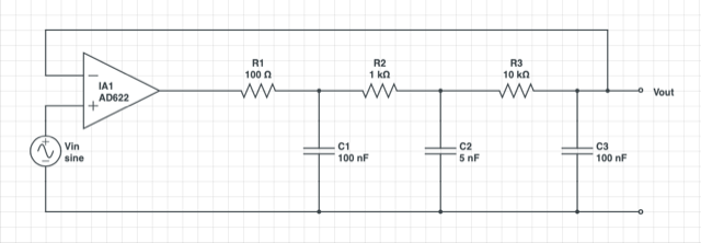
- Construct the circuit shown in the diagram below
- Connect the output of a signal generator to channel 1 of an oscilloscope and also to the input of your circuit.
- Connect the output of your circuit to channel 2 of the oscilloscope.
- Set the function generator to produce a 100 Hz, square wave output with an amplitude of 100 mV.
- Adjust Rgain so that the system response is slightly overdamped.
- Measure the frequency response of the system as you did in part 1 of the electronics bootcamp.
- Find the transfer function, the undamped natural frequency, and the damping coefficient.
- Plot the data and transfer function (as you did in part 1)
- Adjust Rgain so that the circuit is critically damped and repeat steps 6-8.
- To ensure that the system is critically damped, turn the potentiometer knob until you see a slight overshoot in the response and then turn it back until the overshoot just disappears.
- Adjust Rgain so that the circuit is slightly underdamped (two or three overshoots) and repeat steps 6-8.
- Adjust Rgain so that the circuit is underdamped with at least a dozen or so overshoots and repeat steps 6-8.

