Difference between revisions of "Assignment 6, Part 2: electronics written problems"

From Course Wiki
Jump to: navigation, search
 
Line 1: Line 1:
 +
{{Template:20.309}}
 
__NOTOC__
 
__NOTOC__
  
Line 38: Line 39:
  
 
{{Template:Assignment 6 navigation}}
 
{{Template:Assignment 6 navigation}}
 +
{{Template:20.309 bottom}}

Latest revision as of 05:20, 5 April 2020

20.309: Biological Instrumentation and Measurement

ImageBar 774.jpg


This is Part 2 of Assignment 6.

Ideal elements


Pencil.png

For each of the ideal, two-terminal elements listed below, show the symbol, label the terminals, indicate the direction of current flow, write the constitutive equation, and find an expression for the impedance, $ Z(\omega)=\frac{V}{I} $. (To find the impedance, substitute $ V=Ae^{j\omega t} $ into the constitutive equation and solve for $ \frac{V}{I} $ as a function of $ \omega $.)

  • Resistor
  • Capacitor
  • Inductor
  • Voltage source
  • Current source


Resistive circuits


Pencil.png

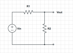
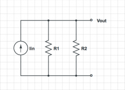
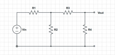
For each of the circuits below, find the voltage at each node and the current through each element.


1 2
Voltage divider.png Current divider.png
3
Ladder circuit.png

Equivalent circuits


Pencil.png

For each of the circuits in the previous problem, find two equivalent circuits — the first one consisting of a single voltage source and a single resistor, and the second one consisting of one current source and one resistor. In both equivalent circuits, the I-V curve at the Vout the port should be identical to the original circuit.


Navigation

Back to 20.309 Main Page.