Difference between revisions of "Aligning the optical trap"
(Created page with "{{Template:PrecisionMeasurement}} {| |- valign="top" | __TOC__ | Laser tweezers based on the ThorLabs OTKB optical trap kit. |} =...") |
|||
| Line 5: | Line 5: | ||
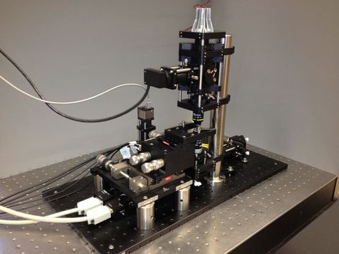
| [[Image:OpticalTrap.JPG|thumb|center|top|480px|Laser tweezers based on the ThorLabs OTKB optical trap kit.]] | | [[Image:OpticalTrap.JPG|thumb|center|top|480px|Laser tweezers based on the ThorLabs OTKB optical trap kit.]] | ||
|} | |} | ||
| − | == | + | ==Setup and alignment== |
| − | === | + | ===Connecting the electronics=== |
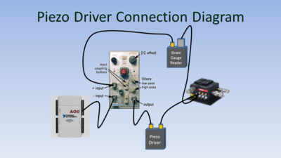
| − | [[Image: | + | [[Image:OpticalTrapPiezoDriverConnectionDiagram.PNG|thumb|right|400px|'''Piezo driver connection diagram for X axis.''' ]] |
| + | Some optical trap measurements (such as Stokes calibration, DNA tether measurement, and force clamping) require precise, computer-controlled movement of the sample. The [http://www.thorlabs.com/newgrouppage9.cfm?objectgroup_id=2386 Nanomax stage] that holds the sample includes piezoelectric elements that can translate the sample over a range of approximately 20 microns in the X, Y, and Z directions. To control the position, a [http://www.thorlabs.com/newgrouppage9.cfm?objectgroup_id=2421 piezo driver] applies a voltage across the piezoelectric element. The driver is part of a closed-loop system that also includes a [http://www.thorlabs.com/newgrouppage9.cfm?objectgroup_id=2423 strain gauge displacement sensor]. The sensor generates a feedback signal that varies linearly with the stage position. | ||
| − | + | The piezo driver can be controlled directly by computer; however, it cannot produce the smooth, complex motions needed for some measurements. Accordingly, an alternate scheme is used to facilitate precise computer control of the stage position. The stage is controlled by a software-generated offset signal from a [http://sine.ni.com/nips/cds/view/p/lang/en/nid/207096 digital-to-analog converter] connected to the computer. A differential instrumentation amplifier with unity gain is inserted in the piezo driver's control loop. The amplifier subtracts a the software-generated offset from the strain gauge reader's output. In response to a change in the offset voltage, the piezo controller adjusts the stage position until the set point is reestablished. The responsivity of the strain gauge reader is about 0.45 Volts per micron. Thus, a one volt change in the offset voltage produced by the DAC results in a movement of about 2.2 microns. | |
| − | + | The offset scheme is implemented on the X and Y axes only. | |
| − | + | <html> | |
| + | <div align="center"> | ||
| + | <table border="1"> | ||
| + | <tr><td> | ||
| + | <iframe src="http://techtv.mit.edu/embeds/23410?size=custom&custom_width=544&player=simple&external_stylesheet=" frameborder="0" width="544" height="338"></iframe> | ||
| + | </td></tr> | ||
| + | <tr><td> | ||
| + | <b><div align="center">Caption</div></b> | ||
| + | </td></tr> | ||
| + | </table> | ||
| + | </div> | ||
| + | </html> | ||
| − | + | --- say something about QPD ---- | |
| − | + | ||
| − | |||
===Remove the optics=== | ===Remove the optics=== | ||
===Collimating and adjusting the fiber port=== | ===Collimating and adjusting the fiber port=== | ||
| Line 34: | Line 44: | ||
<object name="ttvplayer" id="ttvplayer" type="application/x-shockwave-flash" allowScriptAccess="always" allowNetworking="all" allowFullScreen="true" height="336" width="544" data="http://www.kaltura.com/index.php/kwidget/wid/_203822/uiconf_id/1898102/entry_id/1_tojxf237/"><param name="allowScriptAccess" value="always" /><param name="allowNetworking" value="all" /><param name="allowFullScreen" value="true" /><param name="bgcolor" value="#000000" /><param name="movie" value="http://www.kaltura.com/index.php/kwidget/wid/_203822/uiconf_id/1898102/entry_id/1_tojxf237/"/><param name="flashVars" value="autoPlay=false&streamerType=rtmp"/><a href="http://ttv.mit.edu">MIT Tech TV</a></object> | <object name="ttvplayer" id="ttvplayer" type="application/x-shockwave-flash" allowScriptAccess="always" allowNetworking="all" allowFullScreen="true" height="336" width="544" data="http://www.kaltura.com/index.php/kwidget/wid/_203822/uiconf_id/1898102/entry_id/1_tojxf237/"><param name="allowScriptAccess" value="always" /><param name="allowNetworking" value="all" /><param name="allowFullScreen" value="true" /><param name="bgcolor" value="#000000" /><param name="movie" value="http://www.kaltura.com/index.php/kwidget/wid/_203822/uiconf_id/1898102/entry_id/1_tojxf237/"/><param name="flashVars" value="autoPlay=false&streamerType=rtmp"/><a href="http://ttv.mit.edu">MIT Tech TV</a></object> | ||
| − | |||
| − | |||
| − | |||
| − | |||
| − | |||
| − | |||
| − | |||
| − | |||
| − | |||
| − | |||
| − | |||
| − | |||
| − | |||
| − | |||
| − | |||
| − | |||
| − | |||
| − | |||
| − | |||
| − | |||
| − | |||
| − | |||
| − | |||
| − | |||
| − | |||
| − | |||
| − | |||
</html> | </html> | ||
{{Template:20.309 bottom}} | {{Template:20.309 bottom}} | ||
Revision as of 23:42, 1 April 2013
Setup and alignment
Connecting the electronics
Some optical trap measurements (such as Stokes calibration, DNA tether measurement, and force clamping) require precise, computer-controlled movement of the sample. The Nanomax stage that holds the sample includes piezoelectric elements that can translate the sample over a range of approximately 20 microns in the X, Y, and Z directions. To control the position, a piezo driver applies a voltage across the piezoelectric element. The driver is part of a closed-loop system that also includes a strain gauge displacement sensor. The sensor generates a feedback signal that varies linearly with the stage position.
The piezo driver can be controlled directly by computer; however, it cannot produce the smooth, complex motions needed for some measurements. Accordingly, an alternate scheme is used to facilitate precise computer control of the stage position. The stage is controlled by a software-generated offset signal from a digital-to-analog converter connected to the computer. A differential instrumentation amplifier with unity gain is inserted in the piezo driver's control loop. The amplifier subtracts a the software-generated offset from the strain gauge reader's output. In response to a change in the offset voltage, the piezo controller adjusts the stage position until the set point is reestablished. The responsivity of the strain gauge reader is about 0.45 Volts per micron. Thus, a one volt change in the offset voltage produced by the DAC results in a movement of about 2.2 microns.
The offset scheme is implemented on the X and Y axes only.
<html>
|
<iframe src="http://techtv.mit.edu/embeds/23410?size=custom&custom_width=544&player=simple&external_stylesheet=" frameborder="0" width="544" height="338"></iframe> |
|
Caption
|
</html>
--- say something about QPD ----
Remove the optics
Collimating and adjusting the fiber port
Initial laser alignment
Beam expander coarse adjustment
Condenser adjustment
Connecting the piezo stage
Fine adjusting the beam expander
<html> <script type="text/javascript" src="http://html5.kaltura.org/js"></script> <script type="text/javascript">
 mw.setConfig('EmbedPlayer.AttributionButton',false);
 mw.setConfig('EmbedPlayer.EnableOptionsMenu',false);
</script> <object name="ttvplayer" id="ttvplayer" type="application/x-shockwave-flash" allowScriptAccess="always" allowNetworking="all" allowFullScreen="true" height="336" width="544" data="http://www.kaltura.com/index.php/kwidget/wid/_203822/uiconf_id/1898102/entry_id/1_tojxf237/"><param name="allowScriptAccess" value="always" /><param name="allowNetworking" value="all" /><param name="allowFullScreen" value="true" /><param name="bgcolor" value="#000000" /><param name="movie" value="http://www.kaltura.com/index.php/kwidget/wid/_203822/uiconf_id/1898102/entry_id/1_tojxf237/"/><param name="flashVars" value="autoPlay=false&streamerType=rtmp"/><a href="http://ttv.mit.edu">MIT Tech TV</a></object>
</html>


